Continue to Site

Welcome to our site!

Electro Tech is an online community (with over 170,000 members) who enjoy talking about and building electronic circuits, projects and gadgets. To participate you need to register. Registration is free. Click here to register now.

  • Welcome to our site! Electro Tech is an online community (with over 170,000 members) who enjoy talking about and building electronic circuits, projects and gadgets. To participate you need to register. Registration is free. Click here to register now.

12V SLA Battery Load

Status
Not open for further replies.

Suraj143

Active Member
Guys I'm building a 12V SLA battery monitor for various 12V batteries.
Ex:
12V/7Ah
12V/3.12Ah
12V/1.2Ah

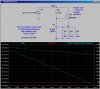
I want to read the terminal voltage while it is loaded by a constant current load.

For the loads I'm going to use resisters high wattage.

I calculated I got these value / wattage resisters to get same amount of current printed on the battery.

To get 7Ah needs 1.7R / 84 Wattts resister
To get 3.12Ah needs 3.84R / 37.4 Wattts resister
To get 1.2Ah needs 1.2R/ 14.4Wattts resister

The problem is its hard to find out such big wattage resisters :(

Any ideas?
 
You can make a constant current load using e.g. a buffered regulator; the power is dissipated in a transistor which is attached to a heatsink (and fan). You could use an LM317 with PNP / PMOS buffer or a TL431 with an NPN / NMOS buffer.
 
Hi friend thanks for the information.

I looked through LM317, but for constant current it has the circuit without transistor.

Iout = 1.25/R

The pass transistor with LM317 has only for constant voltage & not for constant current :(
 
Here is a battery capacity tester I built back in 2003. The two big things on top are "locomotive braking resistors", each rated at 1200W (that is why they are on top; heat rises) :D I bought them at a surplus store just for this project.

This tester will discharge a 12V 35Ah battery in <30min (~70A). I use it to measure the reserve capacity of aircraft batteries during annual inspections.

Since the battery voltage falls off as it discharges, the discharge current is not constant. I have current and voltage monitors going into an A/D converter interfaced to the laptop's parallel port so that it can compute the instantaneous power and it can calculate the total Ah. It can also log the battery recharging cycle, so can plot the charge and discharge profiles, efficiency, etc.

You could also immerse resistors in a liquid with a low boiling point. Causing a liquid to change phase from liquid to vapor soaks up a lot of W.
 

Attachments

  • DSCN1156.jpg
    DSCN1156.jpg
    429.9 KB · Views: 403
Hi friend thanks for the information.
I looked through LM317, but for constant current it has the circuit without transistor.
Then add the transistor. You can simply use the high current voltage regulator circuit it shows (with transistor) and adjust it so that Vout = 1.25V. The excess power will be dissipated in the transistor and the current will be constant.
Iout = 1.25/R
The pass transistor with LM317 has only for constant voltage & not for constant current :(
What is the current if not constant when you have a constant voltage across a constant resistance?
 
The problem is its hard to find out such big wattage resisters.

That's why we make series parallel combinations to achieve whatever we require. Look at a water heater element. 1kW at 120V is 14.4 ohms. Don't forget that automotive Stop Lights are 27W and the running lights are 7W. In parallel, those two elements will draw ... 2.25 A and .583 A.

Don't forget to check and see what the manufacturer is using to determine the aH.

Yes, you can draw the rated current and measure the time it takes to drop to 1.75V per cell. You can build an auto disconnect to remove the load once the voltage reaches 1.75V per cell and begin the recharging process.

Most manufacturers specify the AH at the 10 hour rate or 20 hour rate. So then you are testing the battery with a much smaller load for a slower discharge, hence the need for automatic disconnecting the load .... unless you wish to stand around for 10 or 20 hours.

Recharging is also specified by the manufacturer. It might be at the 1C rate or 0.1C rate.

If you have a specific battery model in mind, read the specifications sheet.
 
Last edited:
Best way to measure the capacity is to time how long it takes the battery to discharge to a cutoff voltage while being discharged by a constant current.

I agree with Joe, only special SLAs will deliver their rated capacity at the 1C rate; more likely 0.1C, meaning that you use 0.7A to discharge a 7Ah battery and its terminal voltage should stay above 11.5V (or whatever the mfg specifies) for 10h.

Here is a circuit that will maintain a fixed voltage of 2.49V across R2 (hence constant current of 2.49/R2) while moving most of the dissipation into the NFET. You can change the current by changing R2. Plots show V(c) and the dissipation in R2 and the NFET as the battery discharges from 13 to 11V.
 

Attachments

  • BatDisch.jpg
    BatDisch.jpg
    112.1 KB · Views: 405
This is what I mean.

There is no way of adding a transistor in constant current mode.

See my drawing.
 

Attachments

  • Voltage LM317.JPG
    Voltage LM317.JPG
    26.8 KB · Views: 401
Hi mike now only I saw your post.Got understood

That means to discharge a 7Ah battery I need 2.5/7 = 0.35 Ohms resister

The resister in watts = 2.5 X 7 = 17.5 Watts

So a decent 0.35R / 20W ceramic resister will be fine to discharge a 7Ah battery @ 1C rate?
 
This is what I mean.
There is no way of adding a transistor in constant current mode.
See my drawing.
Drawing attached showing two constant current circuits with transistor.
 

Attachments

  • Voltage LM317.png
    Voltage LM317.png
    5.3 KB · Views: 887
Hi dougy83 now I understood.

For "R" I'll use 0.18 Ohms (1.25/0.18) = 7Ah

But it will pass full 1.2A current through resister as well as LM317, almost maximum rating from LM317 & the balance will pass through the transistor.

I have to make sure both must be heatsink to gether.
 
But it will pass full 1.2A current through resister as well as LM317, almost maximum rating from LM317 & the balance will pass through the transistor.
The resistor will pass the full current, the transistor will pass almost the full current but the LM317 will only pass some fraction of the current (adjust the 22R to suit or use a PMOSFET to reduce the current through the LM317)
 
...
That means to discharge a 7Ah battery I need 2.5/7 = 0.35 Ohms resister

The resister in watts = 2.5 X 7 = 17.5 Watts

So a decent 0.35R / 20W ceramic resister will be fine to discharge a 7Ah battery @ 1C rate?

Yes, and how about this? The dissipation in the NFet requires a huge heatsink, vapor phase cooling, or an air blower.
 

Attachments

  • BatDisch.jpg
    BatDisch.jpg
    148.8 KB · Views: 361
Here are a few thing to think about:

What will be the highest capacity battery you will want to test?

Do you want to test them against the manufactures specs? They are often different for different manufacture of the "same capacity" battery.

Since you want to test several capacities maybe it should be adjustable instead of changing power resistors?
 
Since you want to test several capacities maybe it should be adjustable instead of changing power resistors?

The other option is building a tester for each capacity. I guess it really depends on the number of batteries your testing per period of time. If you were testing multiple capacities during the week, it would be better to have multiple testers.

For a quick and dirty test, you can use a 50 ohm load on a 12V SLA. connect the meter and measure the no load voltage and then connect the load to measure the loaded voltage. If there is a major drop in voltage, you might want to pull that battery for more testing. Remember, the 12V SLA's fully discharged state is 10.5 volts and the fully charged state is 12.6V. When you connect the 50 ohm load the voltage may drop quickly but settle in fast to a stable reading. If it passes 11V's quickly ... remove it and do an slow charge per your manufacturer's instructions.

Attached is Panasonic's and PowerSonic's SLAhandbook. Enjoy the reading.
 

Attachments

  • Panasonic_Batteries.pdf
    1.9 MB · Views: 549
  • PowerSonic_SLA.pdf
    160.6 KB · Views: 424
Status
Not open for further replies.

Latest threads

Back
Top