Continue to Site

Welcome to our site!

Electro Tech is an online community (with over 170,000 members) who enjoy talking about and building electronic circuits, projects and gadgets. To participate you need to register. Registration is free. Click here to register now.

  • Welcome to our site! Electro Tech is an online community (with over 170,000 members) who enjoy talking about and building electronic circuits, projects and gadgets. To participate you need to register. Registration is free. Click here to register now.

12V Leisure Battery status using 2x LM3914s

Status
Not open for further replies.
The Biggest Problem is you have NO POWER to the LM3914's (Just to your LEDS.)
Pin 3 of Each LM3914 MUST connect to your 12 Volts.

There are Other Problems but I am not prepared to Re-Draw it at this time.

Ideally the Two Internal Resistor Strings should be wired to create ONE Voltage Divider.
NOT TWO, Like you have it.
 
Well, I'll give it a shot. Maybe from this you can draw your schematic. I tried to label the points. Follow the other stuff in the data sheet notes. It may be a little flakey because the steps are so close together. There may be a better way to do it - not sure.:rolleyes:
 

Attachments

  • 3914.png
    3914.png
    147.7 KB · Views: 190
Thank you chemelec and thank you also ronv, I will look at your comments hopefully tomorrow when I have some time.

Thank you again for putting up with a noob, but I'm learning as I go

Gary
 
Not the Voltage Range you want, But Check this out
 

Attachments

  • V-Meter-1.png
    V-Meter-1.png
    9.4 KB · Views: 363
I think the one chemelec posted is better. It has a bigger range.

Edit:

But the input is around 6 volts and I don't see a way for the reference to get that high. Is there a buglet?
 
Last edited:
This should do it:
16LEDVoltmeter.gif

Note: The Rhi input to the resistive-divider has to be at least 1.5V less than the V+ supply, hence the voltage to be monitored (i.e. battery voltage) has to be attenuated. In this circuit R1 and R2 provide an attenuation factor of ~ 0.75. The Rhi and Rlo voltages allow for this attenuation. To keep chip power dissipation within limits Vled must be less than the battery voltage. I have assumed you will use a 7805 regulator to provide Vled. Necessary supply voltage decoupling is not shown (nor are all the LEDs). I have also assumed a 10mA LED current.
 
Last edited:
Here are the calculations for the post #26 circuit:-

Vref = 1.25V.
Voltage range to be monitored = 11.8 to 12.8V.
Scale factor (attenuation) = 0.75.
Scaled voltage range = 11.8 x .75 to 12.8 x .75 = 8.85 to 9.6V.
Hence Rhi(U2) = 8.85 + 20/16 x (9.6-8.85) = 9.79V
....and Rhi(U1) = Rlo(U2) = 8.85 + 10/16 x (9.6-8.85) = 9.32V.
Rlo(U1) = 8.85V.
For ~10mA LED current, (U3 + R3) = R5 = 1k2.
Hence for 9.79V at Rhi(U2), (U5 + R6) = 1k2 x (9.79 - 1.25)/1.25 = 8k2.
So choose U5 = 1k trimmer and R6 = 7k5.
Since U3 + R3 = 1k2, choose U3 = 1k and R3 = 220.
For 9.32V at Rhi(U1), (U4 + R4) = 1k2 x (9.32 - 1.25)/1.25 = 7k8.
So choose U4 = 1k trimmer and R4 = 7k5.

[Voltages should be re-calculated in proportion to the actual scale factor if the factor is not exactly 0.75.
Trimmer adjustments are somewhat interactive. Adjust them in the sequence U5, U4, U3.]

Edit:
BTW, with 10 LEDs drawing 10mA each your battery will run down quickly if the circuit is permanently on ;)
 
Last edited:
circuit6.jpg

Ok so I spent a couple of days looking at all the suggested circuits and I feel like I'm starting to understand these chips, so based upon alec_T's design this circuit should work?

I have added a Dot/Bar switch, do I need another switch for the other pin-9?

Also the LED source is 5V, but I will have 12V as the source, the LEDs are 20mA or 30mA I need to check if that is per LED, but I assume it is the total of all 16 (in pairs so actually 32).

The website that sells the LED unit is down at the moment so I can't check the mA rating: https://www.sparkfun.com/products/11492

Thank you again!

Gary
 
I have added a Dot/Bar switch, do I need another switch for the other pin-9?
Both chips would need to have pin 9 switched if you wanted the choice of bar and dot mode. However, in dot mode there is the added complication of dot-carry (check the datasheet) to ensure LED 10 turns off when LED 11 turns on.

With R3 = 4.7k (instead of the calculated 220Ω) the LED currents for LED1-LED10 will be only ~ 2.5mA each :(

Edit: I've just checked the circular bargraph spec. If I understand it correctly the LEDs are in 4 groups of 4, each group having a single cathode pin; hence only 4 cathode pins in total but 16 anode pins. Unfortunately each 3914 IC is intended for 10 individual LED cathode connections and a common anode connection. So that circular bargraph is unsuitable for your application without drastic circuit modifications (involving the addition of 16 transistors and 16 resistors by my reckoning).
The 30mA spec is almost certainly per LED pair, and is the max rated current. You can see that in bar mode at 10mA per LED pair the display will require up to 160mA! Heat-sinking may be necessary for some components.
 
Last edited:
Hi Alec, I was avoiding mentioning the pnp transistor issue, I was trying to get a circuit which would work on 16 leds then adapt it further, but with what you are saying it looks like the 3914 may not b the way to go on this one? So treating the LEDs as 4 groups of 4, each group has 4 anodes and one cathode.

Should I just mimic the 3914 with separate resistors? (my original idea!)

This is only going to me used occasionally with a momentary push-on switch, I already have designed (and sent off) the designs for laser cutting, so I need to use this LED module for the design.

Thanks for helping me with this.

Gary
 
Should I just mimic the 3914 with separate resistors? (my original idea!)

How do you plan to do this?

If you intend to use That circular display, your only options is to add the driver transistors, or design a suitable Comparator circuit from scratch.

The Current ratings on LED's is just the Maximum rated current.
Just because it says 30 mA, does not mean that they won't operate at 10 mA or less.
 
OR,
Why not just create a Circular PCB and insert your own LED's in that same pattern.
With 16 Cathode connections and only 1 Anode connection.
 
I think chemelec's suggestion is best. However, if you're determined to go with the Sparkfun display then this should work:-
16LEDVoltmeterMod.gif.
The LEDs for only one quadrant are shown. With the pnp drivers you can use a 12V LED-source instead of 5V. The LM3914's are programmed here to draw 1mA current through each transistor base. The previous resistor calculations now go out of the window because the required values are in the same ball park as the resistive dividers in the ICs. According to the spec that is nominally 12k but can be anywhere from 8k to 16k. The dividers are in parallel with the programming resistors. The values I've shown in the mod should give the necessary adjustment for the divider voltages (according to the LTspice simulation).
 
Here is one PCB Example I just created.

This Eliminates all 16 Transistors.
 

Attachments

  • 16-LED.PNG
    16-LED.PNG
    10.7 KB · Views: 214
Last edited:
So, after Alec T's schematic I put this together.
circuit7.jpg
Is this correct? If yes I will order the rest of the components and get the PCB designed/ordered.

I have added 2 switches on the 9th pins for bar/dot mode.
And a Momentary push switch so it isn't on all the time wasting the battery.

Thanks

Gary
 
First you should breadboard that circuit, to make sure it will calibrate for the voltage range you want.

The Dot/Bar Switch should be a DPST Switch.
This will Switch Both IC at the same time.
 
Your schematic looks ok apart from the missing connections and resistor for the dot-mode carry (check the datasheet regarding cascading two ICs). I haven't simulated dot-mode, so don't know if the programmed 1mA current draw will allow it to work. I'll look into that. Do you really want dot-mode?
I agree with chemelec about breadboarding the circuit.
You might also want to allow space on the pcb for an extra resistor or two in series and/or parallel with the divider voltage-setting components in case the values suggested need wider adjustment than the trimmers can provide (unless you are prepared to unsolder and swap resistors). Reality may not correspond with simulation, taking component tolerances into account. Good luck with the build, but considering the very narrow voltage range you will be measuring don't be surprised if the display is jittery or drifts, because of battery voltage fluctuations under load and with temperature.
 
Last edited:
Thanks again,

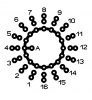
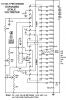
Missing connections? Do you mean the 20k resistor which goes somewhere... between pin 10 an 11 on the 1st IC.
What else have I missed?

I'm not too fussed about Dot mode.
I have added dpst jumpers to the design so I can cap them so I can see how it works once im happy I will leave it in one of the modes.
There is one extra modification I would like - I might be pushing my luck...

It would be great if when it is turned on rather than all LEDs lighting up instantly there would be a very slight delay, so you turn on and they 'fill up' turn off and they 'empty' I would guess different value capacitors would be the way to go? I know this is adding more complexity, but it would look good. What do you think? Is it simply a matter of throwing in a few capacitors?

To think it through... turn on, capacitor fills causing delay, led 1, then 2 then 3... turns on...
turn off - smallest capacitor empties the quickest causing led 1 to go off first...
I see a problem, hmmm.... an interesting effect which I could live with, but would be nice for led 3 to go off followed by 2 then 1...

Your thoughts?

Oh and believe me I don't plan to do any other complicated circuits anytime soon, an this really is the last finishing touch - I am really really gratefull for your help, both chemelec and alec_t
I will post pictures of it finished (when we get there) - maybe a youtube demo too.

I am going to use OSH Park to make the circuit board (after bread boarding), just got a few back and they look great, great quality and cheap. Don't know if you have used them? https://oshpark.com

Gary
 
To think it through... turn on, capacitor fills causing delay, led 1, then 2 then 3... turns on...
turn off - smallest capacitor empties the quickest causing led 1 to go off first...
I see a problem, hmmm.... an interesting effect which I could live with, but would be nice for led 3 to go off followed by 2 then 1...

A Good Quality, "Low Leakeage" cap across R2 should do that. (Try 100uF)
But the Timing between the LED's Lighting, Won't be Linear. It will be LOG.

If I can get my WorkBench free tomorrow, (Wife is making transformers now) I will breadboard it up to see if it works for the voltage range you want.
I have All of these parts in stock, soon to go in the garbage.
 
Thanks chemelec,

I am making a list of components, I was looking at resistors yesterday, they have a Watt rating, would 0.25W be ok? I have no idea!
https://uk.farnell.com/jsp/search/productdetail.jsp?sku=2329932
Also there are so many different models of transistor, I need a PNP, would these be ok?
https://uk.farnell.com/jsp/search/productdetail.jsp?sku=9558527

Perhaps this type of cap, 25V 100uF, no idea how to know if it is low leakage?
https://uk.farnell.com/rubycon/25ml100mefc8x7/cap-alu-elect-100uf-25v-can/dp/8126399

Thanks
 
Status
Not open for further replies.

Latest threads

New Articles From Microcontroller Tips

Back
Top