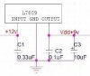
Continue to Site

Welcome to our site!

Electro Tech is an online community (with over 170,000 members) who enjoy talking about and building electronic circuits, projects and gadgets. To participate you need to register. Registration is free. Click here to register now.

  • Welcome to our site! Electro Tech is an online community (with over 170,000 members) who enjoy talking about and building electronic circuits, projects and gadgets. To participate you need to register. Registration is free. Click here to register now.

12v DC to 9v DC

Status
Not open for further replies.

BigE4u

New Member
I have a +12v@1.5a wall adapter plug that i'd like to use in conjunction with a L7809 regulator to use with home grown projects. Im not sure what kind of filtering circuit that is required, so will the circuit in the included picture do or is there more involved? thanks
 

Attachments

  • 12v to 9v.JPG
    12v to 9v.JPG
    9.8 KB · Views: 2,229
Last edited:
Put a much larger cap on the input. Something like 100uF at least.

I'm assuming this is an unregulated wallwart?
 
Actually from an electronics parts store, weighs about 2#s and yes, its unregulated.

Info: KCS Industries - class 2 - part# 57D 12 1500
 
Do you know for a fact that the wall-wart has a filter capacitor in it? Most do not. All they have is a transformer and a full-wave rectifier. If so, then the input cap to the 7809 will have to be huge, on the order of 2000uF.

At 1A load, the sag during 8.333ms for a 2000uF cap is 4V, which is about as much as the 7809 drop out voltage could tolerate.
 
Its not from walmart, its from some electronic store that sells many individual electronic parts and components. As for as knowing if there is a capacitor inside or not, cant tell, the case is snapped together sealed, no screws.
 
Connect a load resistor, like 15 Ohm (>10W) to it. Measure the voltage across the resistor using both the DC and AC Volts mode on your Multimeter. The AC Volts will tell you if there is a capacitor or not. An O'scope would be a better way of making the measurement. Report back.
 
I understand measuring with the DC side with the DMM, but how does using the AC side figure into this?

Ps- Excuse the wall-mart reply, thats what it looked like you said, i see now its wall-wart.
 
If there is no capacitor in it, the AC ripple across the resistor will be almost as big as the DC component.
 
When you say "ripple", you mean the voltage will fluctuate more without a capacitor present and it'll be more stable with a capacitor present under load?
 
Compare these two cases.
 

Attachments

  • Ripple.jpg
    Ripple.jpg
    200.8 KB · Views: 944
The "Ripple" is a left over AC component, the filter capacitor makes the signal more DC, as you increase the load the ripple increases and as you increase the filter capacitor the ripple decreases
 
Point taken... i'll see about getting that 15Ω(>10w) resistor and post back as soon as i can. thanks

Ps- If i find it has no capacitor or just want better filtering, what would be the recomended value(s) to use for the entire circuit shown.
 
Last edited:
A 4700 µF, 25 V capacitor would be a good start. A bigger voltage or capacitance would improve reliability or ripple.

You could use a 10 W car bulb as a load resistor to see if there is a capacitor inside the transformer.

We've all assumed you are needing about 1 A at 9 V, but you never said what you are powering. It is the load current, not the transformer's rating, that controls the size of capacitor needed. If the load is much less, you can use a smaller capacitor.
 
Place to start. Note the increase in ripple across the 2000uF capacitor when the load is turn on. I used an 7805 because I didn't have a Spice model for a 7809.
 

Attachments

  • 9Vsupply.jpg
    9Vsupply.jpg
    210.8 KB · Views: 499
Using a 10w car light bulb as the load resistor is a good idea as well, i didnt even think of that one. I intend to power small electronic projects on a breadboard, having up to 1a available with 9v is all i need. My other wall adapter has switchable voltages(3/4.5/6/9) @ 300ma tops, it has served its purpose till it went belly up, shows 14v across the board.

Ps- Nice piece of software you got there MikeMI.
 
Since i didnt have a 15Ω(>10w) resistor on hand, i did have a new 12v car tailight bulb to use and heres what i got...

DC readings
No Load: 15.59v(+/-1)
Under Load: 11.38v(+/-1)

AC reading
No Load: 0.00(+/-1)
Under load: 0.00(+/-1)

Ps- Correct me if im wrong, but the loaded voltage is alittle low IMO
 
If the tail light lamp is the one with two filaments (1157?), the two filaments are ~1.5A and 2.2A respectively.

I do not understand the ac readings at all; with no built-in filter capacitor, I would have expected about 6-7Vrms; with a built-in capacitor about 1-2Vrms.

Are you sure your meter is working?

Only other possibility is that your supply is regulated, but then why did it drop so much when loaded?
 
I dont see how it can be regulated if the unloaded voltage is 3v+ over the 12v rating and dropped a good amount when loaded. I wasnt to sure how the AC readings would read or even work with a standard DMM set in AC mode(auto) but thats what i got. The bulb i used is a 1157 dual filament, but i used the brighter of the two to get the most out of the loaded readings.

Meter: RadioShack DMM 22-163
 
Most wallwarts do have a built-in capacitor, although it's normally undersized for most applications so assume it doesn't exist as you don't know its capacitance. For an output current of 1A and a 9V regulator, you'll need a 2,200:mu:F capacitor.
 
Status
Not open for further replies.

Latest threads

New Articles From Microcontroller Tips

Back
Top