John Potter
Member
Since my first thread on this Forum a few months ago quite a lot has happened. Firstly I must thank spec for all is help and advice. He has the patience of a saint and can come down to the level of a moron.")

Secondly a slow realisation of what building a power supply means has occurred. The last thread - '2N3055 and heat' helped a great deal and thank you to all those that posted comments. For those that like me are complete novices I'll post here what I have found during what has been quite a steep learning curve, I'm still in bottom gear though.
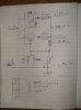
Below is the circuit that spec has designed using the 52V DC toroidal transformer I bought. I wanted a 36V DC power supply but forgot 1.4141.

I don't understand all of the circuit and spec suggested we go through that here later.
One change has been made though. The old PC power supply cases :-


Have been been superseded by a windfall:-

The above was a 100V/70V, 120 Watt RMS - 160Watt max, 2% THD mono line amp that a pint of beer at a pub didn't do any good. The transformer has a 38V DC output at about 8A. As far as I can tell apart from the lovely beer stains the transformer, bridge rectifier, caps, etc. are fine. There is provision for a 24V DC 9A emergency input. The beer stains will remain as they are 'real English ale' and seem quite happy where they are.
For those that are interested this is what it looked like originally :

Slightly to the right of the thermal device on the heat sink you will find a rather toasty resistor on the PCB which is part of the thermal device circuit. Right in front of the small black heat sink, lower left, there is a very toasty 1W resistor.
This unit was a German Monacor PA-900 that despite it's mature design I believe is still in production since the 1980's. My only comment about it's construction is that they must have been to a beer festival when they soldered some of the components in. Pi**ed one might say.


This particular PA-900 is just over 2 years old according to the QA label.
A modification to the original circuit is the addition by spec of a Negative Voltage Generator as the PA-900 transformer is not centre tapped.

One of the selling points Monacor make is that their cooling system for the power transistors requires no fan. As can be seen in the plan view of the open case there are slots below the heat sink and a large area of the top is vented to allow refreshment.
I now have a minor problem. Do I continue with the 2N3055's which could be made to fit this heat sink although with some difficulty or use the existing TIP35C transistors. The 2N3055 is rated at 150C and the TIP35C at 125C. As this was a 120Watt amplifier am I correct in assuming it could be used as a 120Watt power supply with the TIP35C ? It even seems to have the 1 Ohm balance resistors on the TIP35C's ?
I would also like to keep the 2N3055's and the heat sinks I got for them for a further project - an amp. Yes, I'm hooked.
Incidently I found the ABL website that has quite a nice interactive heat sink calculator. I can understand why most people don't like fans but I do. Every PC has one and should there be problems a thermal device, as used in the PA-900 above, should mitigate any damage. The increased efficiency in cooling is quite considerable. Finding a suitable fan is a problem, all the new super quiet fans are just low powered with large tip clearances. Large tip clearance is the mark of a poorly designed fan.
I have phoned ABL and they were very helpful and knowledgeable.
https://www.abl-heatsinks.co.uk/index.php?page=extrudedproduct&product=165
I am now at a point where I can either use the TIP35C or the 2N3055 transistors. I have managed to follow the printed circuit board of the old line amp and towards the TIP35C transistors it almost looks like a power supply. I could use that part of the board.
I have no experience with power supplies at all, I have managed to get 2 LM338's in parallel to work after several attempts. Any advice about which power transistors to use would be very much appreciated.
On a lighter note :- (actually a very, very heavy one)


The first transformer is from a small arc welder rated at 80A 40V AC (55DC) but 20A (1100W) is probably nearer it's continuous rating.
The second transformer was a battery charger / starter (electronics destroyer) and rated at about 100A continuous at roughly 15V DC. (1500W)
I make that about 36 x 2N3055's for the first and 50 for the second at 30W/2N3055.
Anyone like to calculate the number of 20mA 2V red LED's they would light ?
Any comments very welcome.
Secondly a slow realisation of what building a power supply means has occurred.
The last thread - '2N3055 and heat' helped a great deal and thank you to all those that posted comments. For those that like me are complete novices I'll post here what I have found during what has been quite a steep learning curve, I'm still in bottom gear though.Below is the circuit that spec has designed using the 52V DC toroidal transformer I bought. I wanted a 36V DC power supply but forgot 1.4141.
I don't understand all of the circuit and spec suggested we go through that here later.
One change has been made though. The old PC power supply cases :-
Have been been superseded by a windfall:-
The above was a 100V/70V, 120 Watt RMS - 160Watt max, 2% THD mono line amp that a pint of beer at a pub didn't do any good. The transformer has a 38V DC output at about 8A. As far as I can tell apart from the lovely beer stains the transformer, bridge rectifier, caps, etc. are fine. There is provision for a 24V DC 9A emergency input. The beer stains will remain as they are 'real English ale' and seem quite happy where they are.
For those that are interested this is what it looked like originally :
Slightly to the right of the thermal device on the heat sink you will find a rather toasty resistor on the PCB which is part of the thermal device circuit. Right in front of the small black heat sink, lower left, there is a very toasty 1W resistor.
This unit was a German Monacor PA-900 that despite it's mature design I believe is still in production since the 1980's. My only comment about it's construction is that they must have been to a beer festival when they soldered some of the components in. Pi**ed one might say.
This particular PA-900 is just over 2 years old according to the QA label.
A modification to the original circuit is the addition by spec of a Negative Voltage Generator as the PA-900 transformer is not centre tapped.
One of the selling points Monacor make is that their cooling system for the power transistors requires no fan. As can be seen in the plan view of the open case there are slots below the heat sink and a large area of the top is vented to allow refreshment.
I now have a minor problem. Do I continue with the 2N3055's which could be made to fit this heat sink although with some difficulty or use the existing TIP35C transistors. The 2N3055 is rated at 150C and the TIP35C at 125C. As this was a 120Watt amplifier am I correct in assuming it could be used as a 120Watt power supply with the TIP35C ? It even seems to have the 1 Ohm balance resistors on the TIP35C's ?
I would also like to keep the 2N3055's and the heat sinks I got for them for a further project - an amp. Yes, I'm hooked.
Incidently I found the ABL website that has quite a nice interactive heat sink calculator. I can understand why most people don't like fans but I do. Every PC has one and should there be problems a thermal device, as used in the PA-900 above, should mitigate any damage. The increased efficiency in cooling is quite considerable. Finding a suitable fan is a problem, all the new super quiet fans are just low powered with large tip clearances. Large tip clearance is the mark of a poorly designed fan.
I have phoned ABL and they were very helpful and knowledgeable.
https://www.abl-heatsinks.co.uk/index.php?page=extrudedproduct&product=165
I am now at a point where I can either use the TIP35C or the 2N3055 transistors. I have managed to follow the printed circuit board of the old line amp and towards the TIP35C transistors it almost looks like a power supply. I could use that part of the board.
I have no experience with power supplies at all, I have managed to get 2 LM338's in parallel to work after several attempts. Any advice about which power transistors to use would be very much appreciated.
On a lighter note :- (actually a very, very heavy one)
The first transformer is from a small arc welder rated at 80A 40V AC (55DC) but 20A (1100W) is probably nearer it's continuous rating.
The second transformer was a battery charger / starter (electronics destroyer) and rated at about 100A continuous at roughly 15V DC. (1500W)
I make that about 36 x 2N3055's for the first and 50 for the second at 30W/2N3055.
Anyone like to calculate the number of 20mA 2V red LED's they would light ?
Any comments very welcome.
Last edited: