Continue to Site

Welcome to our site!

Electro Tech is an online community (with over 170,000 members) who enjoy talking about and building electronic circuits, projects and gadgets. To participate you need to register. Registration is free. Click here to register now.

  • Welcome to our site! Electro Tech is an online community (with over 170,000 members) who enjoy talking about and building electronic circuits, projects and gadgets. To participate you need to register. Registration is free. Click here to register now.

10 LEDs lit it up acording to a potentiometer

Status
Not open for further replies.
Hy,

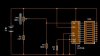
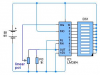
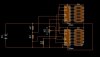
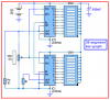
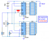
I want to build a circuit based on 10 leds & pot
My question is how can I make all those leds to light up acording to the potentiometer.

When I have the pot set to minimum i want all leds down,when is set to middle only first 5 leds to be lit & when all leds are lit pot is set to maximum

Anyway i think u get the idea.I want to build such a circuit because i want to include it in my amp.

Anyone knows such a circuit, ICs or links to all this?

Thx Adrian,
 
Try LED bar ICs.

They do a great job.

The make a bar of LEDs light acording to the input.These are IC built for this purpuse.They are mostly used in radios to indicate loudnes.
 
I do not need a vu-meter or anything like this.I just want make a circuit in such way, when i rotate the potentiometer to maximum those 10 leds has to be lit to the last and when turn the potentiometer to 0 all leds i want to be off

U got the ideea? I keep searching for several months over the net and I found nothing or maybe I do't know how to search :D

Great respect Adrian,
 
adrianbodor said:
I do not need a vu-meter or anything like this.I just want make a circuit in such way, when i rotate the potentiometer to maximum those 10 leds has to be lit to the last and when turn the potentiometer to 0 all leds i want to be off

U got the ideea? I keep searching for several months over the net and I found nothing or maybe I do't know how to search :D

As already suggested, bar graph IC's do EXACTLY what you want, try looking at the LM3914 which has linear steps, which is what you want, the LM3915 has log steps (for VU use) and wouldn't be suitable.

You could also do it with a PIC, but it hardly seems worth it when exactly the right IC for the job is freely available - and simple to use!.
 
Hint: Apply DC across the pot and the LM3914 bar-graph IC will display the DC voltage of the pot's slider.
 
here you go, vr1 should be 6.5MΩ or equivalent to the P.D.
 

Attachments

  • variable_resistor_baragraff.jpg
    variable_resistor_baragraff.jpg
    16.2 KB · Views: 987
Hi Daniels,
Nice try, but an LM3914 doesn't work like that:
1) Your extremely high value pot has an odd value and its resistance is much too high.
2) The battery voltage changes as the battery voltage runs down, and if the pot is connected to the battery then the display to also change.
3) With the voltage reference's output connected to the adjust pin, the reference voltage is 1.25V and since the RH is connected to the 1.25V then your display would indicate max for most of the rotation of the pot.
4) A resistor is not needed at the lower pin of the pot.
5) A resistor is not needed in parallel with the pot.

Instead, it should be connected like this:
1) Any linear pot can be used from 10k to 1M.
2) The pot is connected to the 1.25V regulated reference voltage that doesn't change.
3) The pot will control the display linearily, from zero to max.
 

Attachments

  • variable_resistor_baragraph.png
    variable_resistor_baragraph.png
    44.8 KB · Views: 921
well, your idea works much better than mine. thanks for the correction.

btw: i am pretty bad at thinking up ideas myself.
 
try this curcuit then it works perfectly and for the 160Ohm resistor just make one up from smaller resistors and it doesnt matter whan size VR1 is!
 

Attachments

  • variable_resistor_baragraff_778.jpg
    variable_resistor_baragraff_778.jpg
    29.1 KB · Views: 877
Hi Daniels,
160 ohms is a standard 5% value.
You are clever to use 20 steps in your bar-graph circuit. :lol:

Your sim isn't smart enough to know:
1) The voltage of the battery will drop over its life and since a divided version of the battery voltage feeds the RH and RL terminals of both LM3914 ICs in series, but the pot's voltage is regulated, then the display will read too high as the battery voltage falls.
2) You have the OUT terminals of both ICs connected together with a 1k load resistor common to both. Therefore the IC with a slightly higher reference voltage will be bright because it will have current in the 1k resistor but the other IC with the slightly lower reference voltage won't have any current and will be extremely dim.

You should have only one IC supplying a regulated 1.25V to the pot and the series'd RH and RL like this:
 

Attachments

  • 20_segment_baragraph.png
    20_segment_baragraph.png
    87.9 KB · Views: 833
danielsmusic said:
hmmm. your design doesn't go up to the top bar. :? why is this?
Hee, hee. :lol: Because your stupid sim program is smarter than me! :lol:

I forgot that the top bar lights only when the SIG voltage exceeds the voltage on the upper IC's RH pin. :oops:
Since the total resistance of both dividers is 24k and the max input offset voltage is 15mV, and the switching between bars needs another 5mV for them to be bright, then 390 ohms added in series with the divider will provide the required 20mV.
 

Attachments

  • 20_segment_baragraph_187.png
    20_segment_baragraph_187.png
    88.3 KB · Views: 788
so my sim prog is good for something... finding other peoples mistakes! :lol:
 
danielsmusic said:
so my sim prog is good for something... finding other peoples mistakes! :lol:
But it doesn't know that a battery's voltage drops as it is used, and it doesn't know that two LM3914's have slightly different reference voltages.
 
can you show me shematic on how to ajust the baragraff display driver just by changing the signal voltage
 
danielsmusic said:
can you show me schematic on how to adjust the baragraph display driver just by changing the signal voltage?
Do you want it to display an external signal's level? It won't perform very well with a music signal:
1) The LM3914 has equal linear steps between its LED thresholds. The LM3915 is more suitable to display music levels because its steps are spaced logarithmically, like your hearing.
2) The display is instantaneous, so it will flicker dimly all over the place. For it to display the levels of music clearly then you should add the Precision Half-wave Peak Detector circuit (or the full-wave one) to the input as shown in the datasheet for the LM3915.
 
Status
Not open for further replies.

Latest threads

Back
Top