Continue to Site

Welcome to our site!

Electro Tech is an online community (with over 170,000 members) who enjoy talking about and building electronic circuits, projects and gadgets. To participate you need to register. Registration is free. Click here to register now.

  • Welcome to our site! Electro Tech is an online community (with over 170,000 members) who enjoy talking about and building electronic circuits, projects and gadgets. To participate you need to register. Registration is free. Click here to register now.

0-5v output to 233-40 ohms linear circuit for fuel press. gauge

Status
Not open for further replies.

Savannarail

New Member
Hi guys,

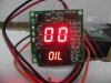
The digital gauge Mfgr said I could use their digital oil pressure gauge for fuel pressure. I bought the oil pressure gauge (thinking I could use their Oil Pressure sender for fuel (since they didn't say anything to the contrary). I changed the legend and made the dash. When the time came to wire everything up, wanting to be sure the oil pressure sender was OK to use with fuel, I called the gauge Mfgr to verify or to get a sender for fuel pressure and they told me they do not have one for fuel and should NOT use their oil pressure sender for fuel.

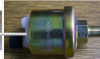
The gauge Mfgr said to get a "40-233 ohm sender" so I searched the web and found one from glowshift gauges, but the resistance values were from 10-180 ohms so I bought it thinking to just add a resistor inline to move the range up to the approximate output range. Well I double checked the ohm range of the oil press. sending unit and it actually goes from 233 ohms @ 0 PSI to 40 ohms @ 100 PSI, which is REVERSE from what I was led to believe. Checking the glowshift sender, it does go from 10 ohms @ 0 PSI to 180 ohms @ 100 PSI. Now I'm stuck as there doesn't seem to be a sender to work with this gauge.

There is a 3 wire Fuel Pressure Sender (FPS) hooked up that uses 5v reference and outputs a linear 0-5 volt reading that the ECU uses and translates into pressure.

A possible solution would be to find a circuit or device that can convert the 0-5v output into a linear 233-40 ohms output, or close to it. The FP Gauge does not need to be 100% accurate as I only need to know if the fuel pressure drops under boost to back off the throttle to prevent the engine from grenading. As long as it is close, say 5-10% off, it will be fine.

Changing out the gauge is not an option since there are 9 other matching gauges custom built into the dash.

Any help would be greatly appreciated.
 
What the gauge is doing is its' using the sender ohm range as a voltage divider to determine the sender pressure 'value'. Thus what you need to do is to place a233 ohm resistor on the gauge input and measure the voltage across it and do the same for the 40 ohm value.
Now you have the voltage range the gauge is looking for.
Then all you need is a low impedance output circuit (emitter follower type) driven by an opamp with gain, feedback and offset set to deliver the suitable voltage range (to the gauge input) based on the sender you have.
Do up an LTspice sim for it and then build it and you're good.
 
Thanks Mosaic,

That seems to make sense, well at least most of it. I can find the voltage the gauge needs, by your instructions, that's easy for me to do but as far as following the rest of your solution, well, I am a "follow the directions" person which can make a printed circuit board from scratch with a schematic or wire up a ECU, but again with complete directions or a schematic - I unfortunately do not have a degree in electronics of any sorts. The rest of your solution, if I have to be blunt and swallow my pride, is a little bit beyond my capabilities.

I have attached a pic of the gauge that I am using for fuel pressure and the oil pressure sender with 1 terminal on it for reference.

Is there a schematic out there or anything that I can follow to make this and change it to meet my needs ?
 

Attachments

  • Intellitronix gauges  oil Press.jpg
    Intellitronix gauges oil Press.jpg
    40.2 KB · Views: 280
  • Oil Pressure sender.png
    Oil Pressure sender.png
    776.5 KB · Views: 255
Ok, lets work with the available 0-5V signal then from the installed OEM sender.
Do you 'know' or can you determine (using a subbed variable 0-5V supply) the scaling vs PSI or Bars?

If you can provide that I can do a sim to verify a schematic for you using common parts to deliver the equivalent output voltage for your dig. meter. BTW do u have a schematic for that meter?
 
Yes,

Pressure transducer (Sender) Output: 0.5V – 4.5V linear voltage output. 0 psi outputs 0.5V, 50 psi outputs 2.5V, 100 psi outputs 4.5V. I unfortunately do not have a schematic for the gauge - Proprietary to Intellitronix.
 
OK if u can use a trimmer pot (500 ohm?) across the input of the digital gauge to obtain the voltage drop across it that gives the 0, 50 and 100 psi output on the gauge I could start building the sim.
 
OK if u can use a trimmer pot (500 ohm?) across the input of the digital gauge to obtain the voltage drop across it that gives the 0, 50 and 100 psi output on the gauge I could start building the sim.
Do you mean in series with the gauge?
 
I went looking at VDO senders, knowing that they go from high to low and low to high resistance. I found this statement.
Warning Notice: VDO pressure senders are not to be used with any type of fuel application. VDO pressure senders may not be used in automotive braking systems. VDO pressure senders are not suitable for use in aircraft.
**broken link removed**

I think your gauge manufacturer said not to use their sender on fuel for liability reasons. Oil pressure senders do occasionally leak. I don't think theirs is any more prone to leakage than another brand. Unless you can find one that is made for fuel, I would use the one that is made for your gauge.
 
BTW, I did a complete turbo controller handling all kinds of 0-5V inputs and outputs as an ECU interceptor, even down to traction controlled boost limiting for torque steering.

I can produce a replica of that Intellitronix Gauge guts in a week working directly from a 0-5V signal. Tempting....as it's a passion of mine....hacking and modding modern cars.
 
Responding to the comment about using the oil pressure sending unit for fuel: Agreed, I will not be using an oil press. sender for fuel. This engine creates 2200 degree exhaust temps so ignition of any fuel leak would be swift and painful.

Mosaic,
I am a tinkerer and can really appreciate the work it took to do that turbo boost controller ! I bought one that worked with my Megasquirt.... I'm not that adventurous or capable... lol

The voltages the gauge sees are: 4.26v @ 0 PSI, 3.45v @ 50 PSI and about 2.05v @ 100 PSI (gauge stops at 99). Getting the 0 and 50 PSI voltages were easy then after fighting to get the 99+ PSI voltage, I thought I would do it mathmatically by: 4.26-3.45= .81 thinking to subtract .81 from 3.45 would give me the voltage for 100 PSI since it was linear, right ?... Not - it was about .59 volts off. I guess I'll stick with building rails..... I fought thru the very very sensitive pot I had and think I got it close for the 100 PSI.
 
Non linear makes for a bit of a prob.
I'll need more points for better mapping, can u get 25psi and 75psi voltages as well pls.
Also let me know the minimum pressure under which an alarm or relay drive output line triggers and u can use to auto-kill the ignition and protect your engine.
This is beginning to look like a micro-controller solution.

EDIT:
I'm getting to play around with a Tesla Model X 75KW SUV soon ....a photovoltaic charge solution is sought.
 
The results are, with relatively good repeatability: 2.05@100, 2.86@75, 3.47@50, 3.95@25, 4.27@0. I also did it in 20 PSI increments starting from 98: 2.2@98, 2.76@78, 3.31@58, 3.71@38, 4.09@18.

I may need a smaller Pot to get better readings as the 2K Ohm is very touchy ! The meter jumps many PSI sometimes with little voltage change. I've checked connections even soldered them to rule out bad connections, then went to a single output power supply to rule out the possible less than perfect pot in the variable voltage power supply.

Solar charge Tesla huh.... Nice !!!!
 
Ok, given what I see the best accuracy requires a micro controller sampling the voltage, averaging and doing interpolation between the known points on a millisecond time scale.
Sender plot.png


EDIT. The output drive from the sender to voltage converter will have to sink about 51mA to 'hold' the voltage for the gauge.
 
Last edited:
It's good to see the voltage vs pressure reading plotted to see a distinct pattern. Interesting solution - I like it.

If it makes it easier, maybe I should focus on getting the accuracy of this gauge in the range that will be used and that is important. Above and below that range is really a reference for seeing pressure rising or falling. Stock fuel pressure is 43.5 psi for the injectors . In the near future, once the engine is tuned and the fear of knock is gone (engine is a 13B Rotary RX7) I will need a little more fuel than the 48lb/hr injectors can deliver at stock pressure, so I will raise the pressure to a minimum of 56.5 PSI to adequately support the desired 300 HP.

If I am looking for accuracy then I might as well build a precise test setup to see what voltage the sender gives at 43.5 and 56.5 air pressure (OR just calibrate the range 40 thru 60 PSI). I do have a digital pressure gauge from Omron that is very accurate. It will take me all of tonight (after work) to get it all set up, but it can be done without much trouble.

Maybe I can use the apparent 5v from the FP Gauge to power the sender (good idea or not ?).

I will wait for your reply before I start the calibration setup in case you have other thoughts.
 
One time I was working on a boat that had VDO electric transmission oil pressure gauges. The owner was concerned that the port and starboard pressures were different by about 20 lbs. Mechanical gauges said they were equal. Trying different sending units only got them within 15 psi. I called VDO and they started making excuses so fast that I wrote them down.

"The higher the pressure, the more inaccurate."

"Pressure gauges are to warn of low pressure."

"15 psi over a range of 350 is less than 5% error."

I think this one is their company motto:
"A man who owns more than one clock, doesn't know what time it is."

"Live with the error."

I have kept this list in my wallet for a lot of years. I think of it every time I talk to a company's excuses department.
 
LOL I agree with that for the most part.... Murphy's Law always tries to get me so what works for me is to get the best results economically possible and deal with the smaller variance.

I would live with the error but it does need to be somewhat accurate, at least in the PSI range I am using, due to the RX7 engine does not like ANY knock. They will grenade. If I'm under full boost and lose 3-5 PSI, that's enough to lean out and knock - just one good knock will destroy it.

I like Mosaic's solution and will proceed with it, I just didn't want to go thru all that trouble to find the voltage the sender puts out at 43.5 PSI is way off from what that gauge wants for a voltage for that PSI. Thought I would be safe so I wouldn't come back and ask for help to recalibrate the circuit that was just made. I hate it when that happens...lol
 
Status
Not open for further replies.

Latest threads

New Articles From Microcontroller Tips

Back
Top