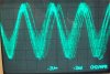
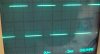
Cheers for that audioguru, turns out somehow I'd managed to reverse the PNP's collector and emitter and I removed the 22pf capacitor and not overheating now however got some issues with the output being very noisy which I do think might have a lot to do with it being poorly shielded/grounded and might clear up once on a proper PCB and in a decent metal enclosure. Strangely it only seems to be affecting sine/sawtooth output and not the square wave.
I've attached some shots taken of my scope screen as I couldnt find an easy way to describe.
What do you guys think? or any suggestions on noise suppression?
I've attached some shots taken of my scope screen as I couldnt find an easy way to describe.
What do you guys think? or any suggestions on noise suppression?

")