Continue to Site

Welcome to our site!

Electro Tech is an online community (with over 170,000 members) who enjoy talking about and building electronic circuits, projects and gadgets. To participate you need to register. Registration is free. Click here to register now.

  • Welcome to our site! Electro Tech is an online community (with over 170,000 members) who enjoy talking about and building electronic circuits, projects and gadgets. To participate you need to register. Registration is free. Click here to register now.

Why Opamp with potentiometer?

Status
Not open for further replies.
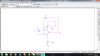
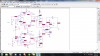
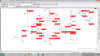
The quiescent current through the lower left op amp positive supply voltage terminal has been shown in Untitled 5. I'm not totally sure is that you want as the quiescent current, I show you all the dc currents in lower left op amp. If it isn't that you meant please tell me, Maybe I have a wrong idea about quiescent current . the voltage of last output is in Untitled 6 and Output of both buffers is in Untitled 7. In untitled 7, -104mv relates to output of lower buffer and -107mv belongs to output of top buffer.
 

Attachments

  • Untitled5.png
    Untitled5.png
    107.1 KB · Views: 231
  • Untitled6.png
    Untitled6.png
    62.3 KB · Views: 189
  • Untitled7.png
    Untitled7.png
    87.9 KB · Views: 182
Last edited:
I want to make the last part of circuit - diffrential amplifier- better. becuase this part doesn't give me the exact difference of inputs. For the circuit shown in untitled 1, Vout equals (V1)* (1+R3/R1) - (V2)*(R3/R1) . V1 and V2 are the lable of inputs. In other words Vout is (V1) + (R3/R1)*(V1 - V2). If I want to have only the term of (V1-V2) what should I change in circuit?
 

Attachments

  • Untitled.png
    Untitled.png
    122.7 KB · Views: 173
Last edited:
The gain of the new circuit should be 1 or nearly so.

In many posts ago we calculated gain of almost half of the circuit, now we add lower section and make some changes. I just want to know how the lower section affects gain of the circuit.
 
Last edited:
I want to make the last part of circuit - diffrential amplifier- better. becuase this part doesn't give me the exact difference of inputs. For the circuit shown in untitled 1, Vout equals (V1)* (1+R3/R1) - (V2)*(R3/R1) . V1 and V2 are the lable of inputs. In other words Vout is (V1) + (R3/R1)*(V1 - V2). If I want to have only the term of (V1-V2) what should I change in circuit?

Hi,

Yes that expression is correct, but that is not the exact circuit we are using in the 'new' amplifier with the two extra buffers.
In our new circuit the output stage has four resistors, not two, and those other two resistors (10k and 100k) make the output expression look like this:
Vout=(V1-V2)*R3/R1

where you can see there is no offset term. So if you want to make your new single op amp circuit work like a differential amp then you've got to add those extra two resistors. Note the feedback resistor has to be the same value as the resistor that goes to ground. In the 'new' circuit with extra buffers the 100k is in the feedback and also another 100k to ground, while the 10k resistors are used for the inputs. That sets the gain of that stage to R3/R1.

The lower section affects the gain by using the input to the lower section as well as part of the input of the upper section.
For example when the inputs are both the same voltage then both sections produce the same output so the difference is zero, but when the lower section input is zero the lower section only gets current from the upper section so it inverts the upper section output to produce it's own output.

The output stage takes the difference of the two section outputs and amplifies it by a factor of 10 (with 100k and 10k resistors).
 
So what's the problem of this circuit that doesn't give us the correct gain? You said something is wrong in it :-(
 
Last edited:
Hello,

You had said that you were not getting the right output although the connections do look right.

Test this again, using 1vdc on the top and 0vdc on the bottom. You should get -1v (ro nearly that) at the output.
With 1vdc on the bottom and ovdc on the top. you should get +1v (or nearly so) at the output.
Test with other combinations like 1v on the top and 2v on the bottom, where the difference is +1 so you should get +1v at the output.
2v on the top and 4v on the bottom should produce nearly +2v output, etc.

You dont have to show waveforms for DC outputs, just the static values shown on the schematic should be ok.
 
Test this again, using 1vdc on the top and 0vdc on the bottom. You should get -1v (ro nearly that) at the output.
Voltage of output is -0.013.

With 1vdc on the bottom and ovdc on the top. you should get +1v (or nearly so) at the output.
Voltage of output is 0.013.

2v on the top and 4v on the bottom should produce nearly +2v output, etc.
Voltage of output is 0.025.

Something is really wrong in this circuit. :-(
 
Hi,

Yes it must be something simple.

Did the models work for a single section alone (upper or lower) ?

To test the upper and lower sections alone, ground the junction of the two 10k resistors (those two that are in series now) on the inverting terminals of the two input op amps. That makes them the same as a single section without the extra added section.
Then if you apply +1vdc to either input you should see about +0.1v at either output.
If you apply -1vdc to either input then you should see -0.1v at either output.
The junction of those two 10k resistors in series must be connected to ground to do this test however.
What this test does is verifies that the upper and lower sections are working ok or not.
Let me know what output voltage you get for both sections, but dont forget to ground the center junction of those two 10k resistors first.
 
You mean, I apply +1dc to both of inputs and see the output of current mirrors or output of buffers because there is no difference between them. if you say so, When I apply +1vdc both of output voltages are 0.1v and for -1vdc both of output voltages are -0.1v.
 
Last edited:
Hi,

If that is when you ground the junction of the two series 10k resistors then both upper and lower sections looks good. You should look now at the output of the buffers to make sure the buffers are working right. If the buffers dont work right, the whole thing wont work right either.

With both buffers putting out the right voltages (+0.1v or -0.1v) then the output should look right too, but to see 1v on the output you have to have a 'differential' input of 1v, not 1v on both channels. The simplest is when the lower channel has 1v and upper has 0v, and when the upper has 1v and the lower has 0v. With these connections (and 10k series resistors still grounded) you should see plus or minus 1 volt on the output. If you dont, then the output differential amplifier is not working.
If the output amp is not working then you have to fix that next.

So try that next, keep the two 10k series resistors junction grounded, apply 1v to the lower section, 0v to the upper section, then measure the outputs for BOTH channels at the output of the buffers again, then measure the output of the final amplifier.
 
Hi,

Yes it must be something simple.

Did the models work for a single section alone (upper or lower) ?

To test the upper and lower sections alone, ground the junction of the two 10k resistors (those two that are in series now) on the inverting terminals of the two input op amps. That makes them the same as a single section without the extra added section.
Then if you apply +1vdc to either input you should see about +0.1v at either output.
If you apply -1vdc to either input then you should see -0.1v at either output.
The junction of those two 10k resistors in series must be connected to ground to do this test however.
What this test does is verifies that the upper and lower sections are working ok or not.
Let me know what output voltage you get for both sections, but dont forget to ground the center junction of those two 10k resistors first.

I'm so sorry. I did this test one more time. For +1Vdc, I got ( - 0.103v ) at the output of both current mirrors. For -1Vdc, I got (- 0.105v) at the both of outputs. SO Current mirrors don't work ok. In previous post I didn't see the minus when inputs were +1Vdc. Sorry about that, again :-(

For output of both buffers I got the same values.
For FINAL output, by applying 1Vdc to lower section and 0V to upper the very last output is 0.0124v. 1Vdc to upper section and 0V to Lower final output is -0.0127v. Voltage of UPPER buffer is -0.103V and the lower buffer is - 0.104V.

Actually When the junction of 10k resistors isn't grounded I still got these values at the FINAL output.

Anyway I attached voltages of all parts of circuit when upper input is 1vdc and lower is 0vdc.
We have to correct the current mirrors I have no idea why They don't work right.
 

Attachments

  • Untitled.png
    Untitled.png
    147.9 KB · Views: 190
Last edited:
Hi,

Ok so we've narrowed it down to the current mirrors. But it could be the op amp models, so do you have the model statements handy?

You could try connecting a 10k resistor across the power supply pins of the upper first op amp to see if increasing the quiescent current through the current mirror helps to establish a better operating point. This may or may not help so you have to measure the output of the buffer again for that section.

The ideal operation is that for a +1v input the 10k resistor on the output of the op amp draws a current through the top current mirror of that section and that causes a positive voltage to be developed across the 1k output resistor. The gains are set up such that the output is one-tenth of the input and with the same sign, so we should get +0.1v output when it is working correctly.

I am really suspecting the model now, but i wont jump to that conclusion just yet. If you can provide the model statements we can take a look and see if the model is capable of being used in this manner. If not we might switch to a different model.
 
What do you mean by model statement of the op amp? The schematic diagram of op amp and its electrical characteristics which are in the datasheet of op amp?
would you please tell me one more time where should I add one 10k resistor because I don't understand what you said.
 
The new 10k would connect from the positive supply terminal of the op amp to the negative supply terminal of the op amp. That will increase the quiescent current through the current mirrors. Obviously this only goes for the op amps that have the current mirrors, but you can try it with only one first to start with, just to see if it helps.


The model statement is found somewhere in your simulator software. It may be on a data sheet, but that's not what we want. We want to know exactly what model statements are being used for your software not just some general spice model statement set.
It is usually under some directory but i am not familiar with your exact simulator software so i cant tell you for sure.
Once we see the model being used we can tell if it is suitable for the kind of circuit we are using the op amp in.
You might also try using LTSpice.
 
I don't have LTspice . I use Orcad 9.2 for simulating this circuit.
I don't still have any idea what the model statements are. That's why it's hard for me to search in my simulator and try to find it. But I have one question You mean this circuit doesn't work right because we don't know the model statement? If I have assemble this circuit on a breadboard it's possible to get the right result?
 
The new 10k would connect from the positive supply terminal of the op amp to the negative supply terminal of the op amp. That will increase the quiescent current through the current mirrors. Obviously this only goes for the op amps that have the current mirrors, but you can try it with only one first to start with, just to see if it helps.


The model statement is found somewhere in your simulator software. It may be on a data sheet, but that's not what we want. We want to know exactly what model statements are being used for your software not just some general spice model statement set.
It is usually under some directory but i am not familiar with your exact simulator software so i cant tell you for sure.
Once we see the model being used we can tell if it is suitable for the kind of circuit we are using the op amp in.
You might also try using LTSpice.

putting a 10k resistor doesn't help :-( I hope we can find another way to see why this circuit doesn't work because it seems impossible to find model statements in my simulator as far as I googled it and searched the program.
 
I don't have LTspice . I use Orcad 9.2 for simulating this circuit.
I don't still have any idea what the model statements are. That's why it's hard for me to search in my simulator and try to find it. But I have one question You mean this circuit doesn't work right because we don't know the model statement? If I have assemble this circuit on a breadboard it's possible to get the right result?
I have mentioned about this in my post 34. That most op-amp simulation models (model statements) incorrectly model the power-supply current.
And this is why this circuit will never work in simulation program. In real life the circuit might work, but I would add emitter degeneration resistors into current mirror.

Here you can see the proof.
If I use LT1363 as a op amp LTspice gives the correct result. But if I change the op amp to TL072, I don't get correct result.
 

Attachments

  • 11.PNG
    11.PNG
    29.7 KB · Views: 185
  • Draft1.asc
    5.3 KB · Views: 164
Last edited:
Hi Jony,

Yes i agree that it could be the model itself that is why i was hoping to be able to see the model statements being used in his simulator. Without being able to see that the only suggestion i have left is to try another op amp type.

We can create a model if needed, but im not sure how that particular simulator handles adding new models.
For example the LM358 model i had looked at does model the power supply current well enough to work with this circuit.

So sagh, try a different op amp model, at least for the op amps that have current mirrors (the others wont matter).


By changing op amps of current mirrors to LM358 and adding (250 ohm) resistors to emitters of transistors, output of current mirrors works right. With 1Vdc on both channels I got 0.1v. by applying -1Vdc I got -0.097 v. At the output of buffers I got almost the same value.
But when upper channel is 0Vdc and lower is 1Vdc (between 10k resistors is still grounded ), Output of top buffer is 1.63mv and the lower buffer is 0.1v. Also, the last output is 0.99v.
 
Last edited:
So sagh, try a different op amp model, at least for the op amps that have current mirrors (the others wont matter).

I think I can get correct gain this time if I apply (Vac ) to one input while the other input is grounded. Result of DC sources is right, isn't it?
 
Last edited:
Status
Not open for further replies.

Latest threads

New Articles From Microcontroller Tips

Back
Top