Continue to Site

Welcome to our site!

Electro Tech is an online community (with over 170,000 members) who enjoy talking about and building electronic circuits, projects and gadgets. To participate you need to register. Registration is free. Click here to register now.

  • Welcome to our site! Electro Tech is an online community (with over 170,000 members) who enjoy talking about and building electronic circuits, projects and gadgets. To participate you need to register. Registration is free. Click here to register now.

Why Opamp with potentiometer?

Status
Not open for further replies.
Hi,

I see you had changed that 500k to 10k, but that's still not right.
I'll talk about this one more time.

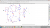
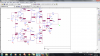
Change R2 and R4 to 10k each.
Ground the right side of R11.
Connect the left side of R11 to the non inverting input of the right side op amp, remove R8.

Note i had updated this post recently because i mistakenly had shown R2 and R4 to be 5k each when really they need to be 10k each.

Testing:
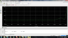
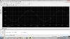
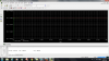
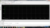
With 1vdc in the top and 1v in the bottom you should see a very small output voltage, in the millivolts or a couple tens of millivolts. Ditto for -1v and -1v.
With 1v in the top and -1v in the bottom, you should see roughly -1v on the output.
With -1v in the top and 1v in the bottom you should see roughly 1v on the output.
 
Last edited:
Hi,

I see you had changed that 500k to 10k, but that's still not right.
I'll talk about this one more time.

Change R2 and R4 to 5k each.
Ground the right side of R11.
Connect the left side of R11 to the non inverting input of the right side op amp, remove R8.

What do I do with the output of lower current mirror? connected to the ground? this circuit is supposed to work differentially I mean when I apply same AC voltage sources to inputs I get zero volt in output. I think the way you change the circuit affects its work.
 
Hello,

The output of the lower current mirror still goes to the left side of R11, dont disconnect that. That means the output of the lower current mirror connects to the non inverting terminal of the right most op amp too.
[see attachment, corrections in green, but ignore voltages]

The theory of operation is such that when the lower section creates a current of say 1ma that current flows through R11 which then makes it 1v, which then goes to the non inverting terminal of the op amp. Thus the right most op amp gets 1v at the non inverting terminal as a result of the lower input voltage.

I tried to tell you this many posts ago. Connect it as i had shown and it should work to at least some degree.
 

Attachments

  • AmplifierWithCurrentMirrors-5b.gif
    AmplifierWithCurrentMirrors-5b.gif
    62 KB · Views: 183
Last edited:
As You see in Untitled 1 I can't get zero volt when both of inputs are 1 volt(ac). Untitled shows the output when one input is 1 volt(ac) the other is -1 volt(ac).Only by changing R3 from 10k to 1k output voltage becomes zero volt.
 

Attachments

  • Untitled.png
    Untitled.png
    89.2 KB · Views: 168
  • Untitled1.png
    Untitled1.png
    91.3 KB · Views: 197
Last edited:
Hello again,

Well it is easier to test with DC voltages first then move to AC later. You should see a better result than that, but it is still not perfect yet.

We have a problem with this circuit, and that is that the current mirrors will only work right if they BOTH see the same impedance on their outputs. One solution would be to use a 1k resistor to ground on the output of BOTH upper and lower section current mirror pairs, then for the output stage just construct a differential amplifier with a gain of 10.

What we have now even with a 1k on the output of the lower section is the lower section looks good, but then the upper section does not have a constant 1k impedance on it's output anymore because the output of the lower section changes the bias point for the upper section output, meaning it's no longer a 1k to ground and therefore it will not work as expected, at least not exactly.

With both outputs having a 1k to ground, that means we can at least get the same output from both upper and lower sections. It's then just a matter of using a differential amplifier (four resistors) unless we can find another way to solve this problem.

I am assuming that you are trying to build an instrumentation amplifier, but normally we dont need current mirrors for that. Without the current mirrors we dont have the problem of imbalanced output impedances on the upper and lower sections.

If you want to try this it is not hard to do. Connect a 1k resistor to ground on each current mirror output, then use a regular differential amplifier with the inputs also connected to the outputs of the upper and lower section current mirrors. The output of the diff amp will then be the difference between outputs of the upper and lower sections. The output amp should have a gain of 10 if R2 and R4 are both equal to 10k.

Another idea is to use the two 1k resistors to ground, then use gain of 1 buffers to isolate those outputs from the output stage inputs thus forcing both current mirror pairs to see the same impedance and at the same time supply the right output voltage. This would be a theoretically ideal solution, while the former is an approximation because the output impedances are only very nearly equal in that solution, not exactly equal.
 
Last edited:
I am now convinced that the OP is trying to implement an analog multiplier. As I said already, the concept of differential is the main one there. Why the actual intention is not being explained upfront, I cannot understand. That's why I stopped simulating anything related with it.

Had I been given this task I would not use current mirrors at all.

Buena suerte.
 
Last edited:
Hi,

Oh ok, i was assuming an instrumentation amplifier. But anyway, here is a quick drawing of the concept i was talking about in my previous post.
Obviously the small resistor network with R6 in it can be simplified to two resistors with the drawback that the diff amp resistors then can not be well matched pairs.

The 10k diff amp resistors 'isolate' the output stage by a factor of about 10 to 1, while voltage follower buffers would isolate it by a factor of about 100000 to 1 which would be better, but at the cost of two more op amps.
 

Attachments

  • AmplifierWithCurrentMirrors-6.gif
    AmplifierWithCurrentMirrors-6.gif
    15.9 KB · Views: 177
Last edited:
What we have now even with a 1k on the output of the lower section is the lower section looks good, but then the upper section does not have a constant 1k impedance on it's output anymore because the output of the lower section changes the bias point for the upper section output, meaning it's no longer a 1k to ground and therefore it will not work as expected, at least not exactly.

This is one parts of what you said, would you please explain it more because it's a little bit unclear to me
 
Hi,

Oh ok, i was assuming an instrumentation amplifier. But anyway, here is a quick drawing of the concept i was talking about in my previous post.
Obviously the small resistor network with R6 in it can be simplified to two resistors with the drawback that the diff amp resistors then can not be well matched pairs.

The 10k diff amp resistors 'isolate' the output stage by a factor of about 10 to 1, while voltage follower buffers would isolate it by a factor of about 100000 to 1 which would be better, but at the cost of two more op amps.

It's the output of new circuit. I don't get zero volt by applying 1ac to both of op amps.
 

Attachments

  • Untitled4.png
    Untitled4.png
    127.9 KB · Views: 174
Hello,

Is that hundreds of nanovolts you are seeing there? That's sure very close to zero. You cant expect to get exactly 0.000000000 volts out with equal inputs, but only close to zero.

As for the 'more' explanation, the two current mirror pairs must have equal output resistances or else they will not produce the same output voltage. You need the same output voltage from both upper and lower sections for equal input voltages for this thing to work right. That means you need equal output resistances (we are using 1k right now) and they must both terminate at the same voltage level (we are using ground).

The simplified theory goes like this:
The input produces a voltage, the voltage produces a current, the current is 'mirrored' in the current mirrors, the current mirrors produce a current in the output resistance (1k), the current in the upper section produces a voltage in the upper section, the current in the lower section produces a voltage in the lower section, the output stage subtracts the upper section voltage from the lower section voltage and amplifies the difference to produce the final output.
 
Hi,

Oh ok, i was assuming an instrumentation amplifier. But anyway, here is a quick drawing of the concept i was talking about in my previous post.
Obviously the small resistor network with R6 in it can be simplified to two resistors with the drawback that the diff amp resistors then can not be well matched pairs.

The 10k diff amp resistors 'isolate' the output stage by a factor of about 10 to 1, while voltage follower buffers would isolate it by a factor of about 100000 to 1 which would be better, but at the cost of two more op amps.

Would you please tell me how can I add the other 2 op amp to make this circuit "better"?
 
Hello,

Here is a drawing showing the buffers .
 

Attachments

  • AmplifierWithCurrentMirrors-7.gif
    AmplifierWithCurrentMirrors-7.gif
    20.4 KB · Views: 178
Thank you so much. I have a little problem with the gain of this circuit. Vsin with amplitude of 1v is only applied to non inverting port of top op amp. As you see in Untitled 1
gain of this circuit has the pick of 12 mv. how can I improve gain?
 

Attachments

  • Untitled1.png
    Untitled1.png
    90.3 KB · Views: 174
  • Untitled.png
    Untitled.png
    99 KB · Views: 178
Hello,


There must be something simple wrong now because it looks like you have everything connected properly.

Try an input of 1vdc this time (not AC), and measure the output of both buffers as well as the very output voltage. Lets see what is going on.
 
Why do you think something is wrong in circuit? Output of both buffers show in Untitled 2. output of last op amp shows in Untitled 3.
 

Attachments

  • Untitled 2.png
    Untitled 2.png
    124.2 KB · Views: 184
  • Untitled3.png
    Untitled3.png
    125.9 KB · Views: 199
  • Untitled.png
    Untitled.png
    143.7 KB · Views: 179
This time 1 Vdc is applied to both of inputs. in post number 93 I applied Vsin only to one input. Input of other op amp has no voltage sources, it connects to a resistor 10k and then to the ground . I 'm not sure this way of applying is correct.
 
Your new circuit is missing a value for R10. It should be 10k ohms.
 
Hello,


There must be something simple wrong now because it looks like you have everything connected properly.

Try an input of 1vdc this time (not AC), and measure the output of both buffers as well as the very output voltage. Lets see what is going on.


Would you please tell me gain of new circuit?
 
This time 1 Vdc is applied to both of inputs. in post number 93 I applied Vsin only to one input. Input of other op amp has no voltage sources, it connects to a resistor 10k and then to the ground . I 'm not sure this way of applying is correct.

Hi,

Yes i meant apply 1vdc to only the upper channel as you did with the AC. The lower channel should have 0v as you did before.

Also, when 1v is applied to BOTH channels measure the quiescent current through the lower left op amp positive supply voltage terminal.

The gain of the new circuit should be 1 or nearly so.
 
Status
Not open for further replies.

Latest threads

Back
Top