Continue to Site

Welcome to our site!

Electro Tech is an online community (with over 170,000 members) who enjoy talking about and building electronic circuits, projects and gadgets. To participate you need to register. Registration is free. Click here to register now.

  • Welcome to our site! Electro Tech is an online community (with over 170,000 members) who enjoy talking about and building electronic circuits, projects and gadgets. To participate you need to register. Registration is free. Click here to register now.

Why in Analog and Digital Filters the phase loss is not so important?

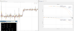
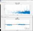
I was studying different types of filters, in particular I came across the ButterWorth Filter, The Tschebyscheff-Filter, the Bessel filter and the Linkwitz–Riley (L-R) filter. I found them on wikipedia. I am dealing with a control system in closed loop so the signal has to not be delayed to much, while analysing these filter I noticed they have a huge phase delay. Why it is not important in analoga and digital filters?
Butterworth Filter.png
 
Why it is not important in analoga and digital filters?
It is important (unless it's not).
In audio applications, nobody cares if the low (less than 30Hz) frequencies are cut off and the passed signal is delayed by half of a wavelength.

It's super critical on a slow-moving analog signal with other over lapping noise - for example, a temperature sensor for a vat in an environment that can be 100ft or more from the control room.

Obviously, this is an old-school example - I haven't seen an analog temp sensor in a production environment in many years.
 
In general what we care about in control systems is their behaviour
to varying electrical conditions, that we maintain design goals for
these changes in control loops (sensors) and environmentals that affect
the control loop. That control loops do not saturate in their handling
of signals for example.

Classic loss of control can be chaotic, oscillation, or breaking desired transfer
functions behaviour. Like classic motor boating in audio gear. One key theory is :


Note discussion is not confined to linear systems, there is a rich area of study,
tons of papers over the years in IEEE, of studies and benefits of non linear
goals and work. I used a non linear filter in a PLL feedback loop to decrease
settling and acquisition in a low freq loop where delays accentuated by pole
frequency locations of the system aggravated the loop response.

Regards, Dana.
 
In general what we care about in control systems is their behaviour
to varying electrical conditions, that we maintain design goals for
these changes in control loops (sensors) and environmentals that affect
the control loop. That control loops do not saturate in their handling
of signals for example.

Classic loss of control can be chaotic, oscillation, or breaking desired transfer
functions behaviour. Like classic motor boating in audio gear. One key theory is :


Note discussion is not confined to linear systems, there is a rich area of study,
tons of papers over the years in IEEE, of studies and benefits of non linear
goals and work. I used a non linear filter in a PLL feedback loop to decrease
settling and acquisition in a low freq loop where delays accentuated by pole
frequency locations of the system aggravated the loop response.

Regards, Dana thank you very much Donna for your response
Thank you very much Dana for your response.
In my case I was trying to eliminate some noise from a sensor but my control loop doesn't allow to go less than 45 degrees of phase shift, unless the system unstabilyzes. In any case what is the non linear filter that you used in your control loop?
 
Phase shift may be important to all applications where true signal recovery is important such as the alignment of harmonics in a pulse wave for radar, sound and data. For servo loops it is even more important as the overshoot is directly related to the amount of phase margin in error correction and the overall stability margin away from resonance.

Generally when the the edge of the filter does not contain any useful signals, the Chebychev filter which provides a steeper edge slope attenuation with higher Q filters dispersed to provide an equal ripple response in the passband but a steep skirt from the higher Q just near the edge of the band. These are not useful for servo's because the higher Q causes a steeper phase change or it's derivative a higher group delay. This also reduces the phase margin in 2nd and higher order feedback loops.

The key to making a servo stable is to compensate the Bode plot to make it a 1st order loop during the transition thru 0 dB loop gain with positive phase margin using a partial derivative filter. This is commonly know as a "Type 2 or 3 phase compensation filter" method for servo loops or sometimes defined as the Kd in a PID servo filter. It is a simple addition commonly used is SMPS servo voltage loops but is best chosen carefully to tradeoff ripple and overshoot stability.

For data recovery the best NRZ filters are called raised-cosine in that they resonate slightly with a zero-crossing at f/2 bit rate for 101010 and this results in reducing inter-symbol-interference (ISI) or random jitter caused by data patterns.

For the lowest group delay requirement, others will choose Cauer , Elliptical or Gaussian filters intended to match the signal spectral shape or bandwidth with minimal phase distortion or the lowest Q or the lowest rate of change of phase spanning over 2 decades centered at the -3dB cutoff.

Any more specific questions, challenges or problems?
 
Last edited:
Why it is not important in analoga and digital filters?
For some applications, the frequency-dependent phase shift of filter functions is very important.

Example 1:

There are some multi-opamp "Biquad" structures (KHN-topology, Tow-Thomas, Fleischer-Tow, Parallel structure,...) which can provide - at the same time (3 output nodes) - the basic 2nd-order lowpass, highpass and bandpass functions.
Using an additional opamp for combining these output signals, we can produce additional filter functions with real zeroes like notch, inverse Chebyshev and/or elliptical functions (Cauer).
In this respect, the phase properties of the mentioned basic functions are very important.

Example 2:

The feedback path of many oscillator circuits contains a passive RC-filter (3rd-order lowpass/highpass, 2nd-order bandpass or even notch).
Such a filter must be designed so that at the desired ocillation frequency the phase shift - together with the sign at the summing junction (inversion or not) - results in positive feedback (zero total phase shift).
 
Last edited:
Any more specific questions, challenges or problems?
Thank you very much all for the support. In my case I am not dealing much with data transmission but rather with the noise caused by a sensor. In the image I show the FFT of the signal, and a trial for simple single,double and triple order filters. Do you any better advice how to clean this signal without losing to much phase? Otherwise my control loop goes unstable.
Some of my collegues suggested that maybe was better to do an electronic filter, rather than a digital one, but don't have much experience over this.
 

Attachments

  • Comparison With First-Second-Third Order Filter.png
    Comparison With First-Second-Third Order Filter.png
    271.3 KB · Views: 54
  • FFT Signal Analysis 1.png
    FFT Signal Analysis 1.png
    114.1 KB · Views: 52
Generally an optimal receiver matches BW to the signal spectrum and attenuates outside. But we do not know the Bode Plot for your system and the LVDS is rather noisy.

You may implement the same filter digitally or analog. Here is a random example, except RC values ought to be scaled R*1k and C/1k. You may compare the gain phase to your cascaded 3 stage filter. Then try to generate a closed loop Bode plot with schematic so we can see the phase margin.

1706824554726.png


To generate a Bode plot break the feedback loop and drive the error input and measure the feedback log voltage vs log f. for amplitude and phase. Use a weak DC feedback if necessary to bias in the middle and excite with a small AC signal.
 

Latest threads

New Articles From Microcontroller Tips

Back
Top