Continue to Site

Welcome to our site!

Electro Tech is an online community (with over 170,000 members) who enjoy talking about and building electronic circuits, projects and gadgets. To participate you need to register. Registration is free. Click here to register now.

  • Welcome to our site! Electro Tech is an online community (with over 170,000 members) who enjoy talking about and building electronic circuits, projects and gadgets. To participate you need to register. Registration is free. Click here to register now.

What's going on with buck converter?

Status
Not open for further replies.
Hmm, well I checked a few things. The unusual voltage control comes from an EDN article - I'd never have thought of it on my own.

I tried 3 alternative chips from the same pack, all gave the exact same result. However after taking it apart and putting it back together, the noise got much worse, showing over an amp of AC in the output on my fancy new meter, for 3A of DC. Something strange now also happening though, with a fair bit of current showing when the shunt set for it's lowest setting, usually about 50mA, now a few hundred mA.

Anyway, I disconnected the bottom 1k2 resistor and replaced it with a 2k2 direct to ground, fixing the output at around 25V. This made exactly no difference to the performance.

I also wondered if the output cap doesn't perform well at the switching frequency so swapped it for a more modern one (albeit much lower value at 1000uF). Also didn't make any difference.

I tried a few different inductors - barrel types but with ferrite cores as far as I can tell. Made very little difference. So I put the cheap toroid back in.

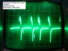
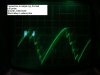
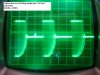
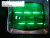
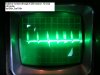
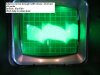
I checked the waveforms again. What I had cursorily looked at before and taken for the switching waveform being rounded at the corners, actually is huge 100Hz ripple. The actual switching current, and voltage on the chip's output pin, is a fairly healthy looking squareish wave, with a lot of jitter. I got it stable by setting a 10mS delay on the 'scope.

It's as though the switcher is taking the bit of ripple on the input and amplifying it by maybe 10 times.
 
So I guess it's down to the construction or the cheap chips (or both).
The other thing I notice is, I've used star earthing for the switcher and load, but in the various manufacturer data sheets it's showing gnd in, switcher, gnd out. So I guess I should try that arrangement.
 
What strikes me is that ground connection to the load and the opamp coming before the flying lead, how long are those? Also some 100nF ceramic decoupling cap added to the input of the chip wouldn´t hurt.
That 10uF cap straight on the output of the opamp seems like a really bad idea, but if it behaves the same with a standard divider than that is not the main problem.
 
If the inductor is colored yellow/white then it should be a Micrometals type 26 powdered iron core.

Details of the core material, as well as other material types are **broken link removed** Click on the material type number for links to performance graphs.

There are knockoff core manufacturers that have copied Micrometals color code, so there is no guarantee that your actual core matches their specs.
 
You mention 100hz ripple, if the i/p voltage dipping below the regulated voltage?
 
Hi,

My question is, are you building the circuit with extra parts in it? If so, try knocking back down to the simplest circuit with only the parts shown on the data sheet. Get it to work that way first, then add the other parts little by little if you can.

The data sheets usually show a sort of star ground. The feedback 1k lower resistor should be close to the IC package. I can show you one of my layouts if you would like to see it, but it is nothing special.
 
Wow, so many responses!
I don't know how to interpret the materials information, so that is something new to learn.

Ok so now I know what saturation looks like on a 'scope - I don't think it's doing it, or if it is it's only slight. I'll have to use another source of square waves for the test jig since I don't have any schmidtt inverters. There is a bit of ringing though.

I have tried reducing it to the simplest form as a stand-alone converter, remaining with the dead-bug build. The input is at least 45 volts (and can go as high as 55) and the output is set to around 25 volts

Good point about caps on op-amp outputs, I'd forgotten all about that. However in the last incarnation before I started stripping it back to basics I did have a 150 ohm resistor in series there which would have stopped it being a problem. However, it was also ok before I put that in.

The chip, it's input and output caps, diode and feedback resistors are clustered as close as I could get them on a piece of plain copperclad FR2. The wire connecting the board to gnd is about 6" long, and it's input power lead is a little longer (I've now also threaded it through a really big ferrite bead). I'll try adding that extra ceramic cap on the input though.

The load is connected via mini croc leads, about 8" long I think, also via my meter so more leads there. The load's gnd lead currently goes back to the main cap and rectifier attached to the mains transformer. I'll try moving it to the copperclad and see what happens. Just wait whilst I do that... hold on...

Ok back again. That made no difference either.

I'll have to try building one on a proper pcb, though I've a feeling it won't be any different. There is a layout on the OnSemi version of the datasheet, so I'll base it on that.

For the time being I'm going to assume it's the cheap converter ICs that are at fault, but I'll have to live with them for now, since the real ones cost £4.43 including VAT. (this is the HV version don't forget) and ultimately I need 2. If it's still wonky I'll get branded inductors. The diode has stood quite a pounding so far, so I don't think I need to use a higher rated one. It hasn't measurably changed, but I suppose I should swap it for a new one just to be sure.

I'm not expecting to run this regularly at full output - chances are most of the time it will be loaded at less than 1A since it's part of a general purpose psu (still in development). If I get desperate I can always put in some kind of over-ride for the adjustment. Ugly method.

I'll try and take some photo's off the 'scope.
 
Right, scope photos attached.
These were taken with the meter showing a big chunk of AC current in with the DC. However, after I took these I disconnected the little voltmeter module I'd been using to monitor the voltage, and it quietened right down :banghead::banghead::banghead: but still dropping significant voltage. The extra muck that was in there doesn't seem to have made any difference to that happening though. Up to about 2A it only loses a couple of volts, but at 3A the 25V output drops all the way to 13V.
 

Attachments

  • scope1.jpg
    scope1.jpg
    47.8 KB · Views: 97
  • scope2.jpg
    scope2.jpg
    35.5 KB · Views: 101
  • scope3.jpg
    scope3.jpg
    49.8 KB · Views: 105
  • scope4.jpg
    scope4.jpg
    46 KB · Views: 92
  • scope5.jpg
    scope5.jpg
    43.5 KB · Views: 90
  • scope6.jpg
    scope6.jpg
    49.3 KB · Views: 97
Ring city.
None of the traces look really bad, except the current through the inductor at load, does your scope go fast enough to make that green haze into a visible wave?, my guess its either really bad ringing or maybe the circuits oscillating where it shouldnt, or its just the pulse width varying a lot filling the screen with the trace, try triggering the 'scope using the other channel as the trigger connected to the switching waveform voltage (assuming its a dual trace 'scope).
Also interesting connecting just a meter makes a big diffrence, maybe theres rf all over the circuit.
Heres another inductor checker without inverters:

https://ludens.cl/Electron/lmeter/lmeter.html
 
Hi,

That one pic looks like sub harmonic oscillation. That could be caused by the wrong type of inductor. Try another inductor even if it is rated lower, and keep the current lower. You really should get a better sourced chip to try too though.

Have you ever gotten one of these converter circuits to work with any LM2576 device in the past ? If not, then you should get at least one or two new chips to try. If you did, then you can get one of those chips and try that.
As i said before, i hand wired one circuit and had no problems. It was on a perfboard with those little etched dip patterns from Radio Shack, 2x3 inches i think, and they still sell them.

Since you are posting pics, you can posts a few close up snapshots of your circuit board front and back, the simplest version that doesnt work right. We can then take a look at your exact layout.
 
It's my first attempt to use any sort of LM257x. For a photo, see post #11 - it's hardly changed since then, just take away the blue wire and change the bottom resistor for one connected to the ground plane instead of the caps. The pre-cursor to this build was an MC34063 with external transistor and a voltage dropper in it's input feed. Thinking about it, I had similar problems, but put it down to the old barrel inductors I was using so didn't give it much thought.
I really like Homo Ludens - his transformer winding section has been very useful.
I had a hard time taking the photos due to the amount of jitter - 10mS delay helped steady the waveform to look at, but it still moved around too much for the camera.The last pic I thought it more useful to show the whole envelope, not just the switching waveform, which doesn't actually look bad. I'm not sure testing the current whilst triggering on the voltage is going to help since the timings are the same.
I'll try to find more big inductors in my junk box. Unfortunately they seem to come in two sizes - too big and too small!
Anyway, rather than build the small pcb just for the switcher, I'm going to rebuild it on perf. board, put some shielding around it, give it a try like that, strip everything off the solderless breadboard and add it to the perf. board, connect them together, then I can work on the other things I haven't quite sorted out yet.
I can't afford better parts to try at the moment. As it's part of a general purpose bench psu project It's not important for it to handle the full rated current. It's just really really annoying. Grrrr.
FYI, the scope is a Cossor CDU 150. It just about goes to 40MHz. Triggering is a bit flakey.
 
Hi,

Maybe you should take Diver up on that offer to send you some for just the cost of postage. They wont be HV versions, but that still will give you a starting point. You havent gotten anywhere doing anything else so it's time to try a completely different strategy.
 
That's a very good point actually. I'll pm him :)
 
You just introduced me to 2 new types of components, i was allready aware of ones made from unobtanium, but now theres too big and too small.
 
All sorts of things come in these types, not just components. Clothes, screws and nails, dogs, houses, spare parts for various purposes - all spring to mind. Even springs, and minds...
 
Status
Not open for further replies.

Latest threads

New Articles From Microcontroller Tips

Back
Top