Continue to Site

Welcome to our site!

Electro Tech is an online community (with over 170,000 members) who enjoy talking about and building electronic circuits, projects and gadgets. To participate you need to register. Registration is free. Click here to register now.

  • Welcome to our site! Electro Tech is an online community (with over 170,000 members) who enjoy talking about and building electronic circuits, projects and gadgets. To participate you need to register. Registration is free. Click here to register now.

What's going on with buck converter?

Status
Not open for further replies.

throbscottle

Well-Known Member
I finally got some extremely cheap (definitely fake, they fail far too easily, but 10 of these were a lot cheaper than 1 real one) LM2576HVT-ADJ buck converters. Input 45-55 volts, output adjusts from about 5v to 45v when the supply allows it.
But the one that's built up at the moment seems to be working properly, except when loaded with more than about 750mA, it gets audibly noisy (kind of mid-high pitched bubbling sound) and the output starts dropping. The output ripple gets massive too (the current at which this occurs varies a bit depending on the output voltage setting). Though I'm sure at one point it worked properly. It will actually deliver well over 3A, just with all this noise and ripple.
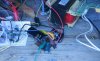
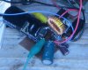
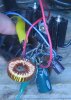
It's build on a piece of plain FR2, smallish heatsink attached (about 7c/w maybe?) doesn't get terribly warm anyway. Gnd and enable pins bent down soldered direct to the copper, diode soldered to the copper and close the o/p pin, i/p and o/p caps soldered as close as I could get them, resistors strung around like xmas lights. I/p cap I can't remember value, but it's supplied down about 7" of wire at the other end of which is the rectifier and 6800uF main cap. Output cap is 3300uF, inductor is 150uH toroid rated for 3A, cheap off eBay (actually it's 160uH).
Load is connected direct to the main rectifier at gnd, output cap at the output.
Voltage control is a little unusual, the resistors of the p/d are fixed, but the gnd end is adjusted over a range of about 0-1.1v, and is decoupled to gnd with 10uF alu. electrolytic + 10nF ceramic in parallel.
I thought it was unstable because of the linear regulator it feeds into, but with this disconnected (so just the voltage control part is used) the same problem occurs (perhaps with an extremely marginal improvement).
Fed up with scratching my head now - any thoughts on this instability?

Cheers :)
 
You didn't say much about the diode??? If you don't get a fast enough one, they sing for fun...

I built my circuit accidentally with a IN4002 instead of a IN5822.. Same real bad output and noisy as hell..
 
I've had fake switchers (they where off-line flyback controlers in my case - can't remember what type exactly, Panasonic I think) fail and semi-fail in all sorts of odd ways. The strangest thing was that every IC in the batch showed a different mode of not-working.
Swap it out for another one and just check it does the same thing...
 
Ok ok I'll draw a schematic, but you get 90% of it off the datasheet. Just disconnect the gnd end of the feedback resistors from gnd and put a control voltage and decoupling cap there. I'll take a photo tomorrow too.
Thanks for the responses though!
Diode is a 1n5822.
Regulation isn't very good. Drops a few volts when load
It actually improved quite a lot after I resoldered the gnd/enable pins on the chip and generally tidied it up. I also discovered that my reference chip was oscillating very beautifully! So I've improved that a lot with a ferrite bead on one leg and a better bypass cap. Still oscillates but much less. Perils of building on solderless breadboard - hoping the real thing is much better.
So now as I turn the dummy load up, it's quiet for about the first 1.5amps, then it howls a bit, then it goes quiet again on the run up to 3A. Although how it behaves depends on the voltage that's set. There seems to be a sweet spot around 20 volts where it's quite well behaved.
 
I had a lot of trouble with inductors on switch mode power supplies, which gave similar symptoms when they failed. I think that there was a partial short in the failed inductors.
A shorted inductor turn would certainly could give some strange results. (it would act rather like a transformer with a shorted secondary).
 
Regulation isn't very good. Drops a few volts when load
Doesn't sound good atall.... It sounds like your voltage control is affected by the output....

When my "fixed" 5v reg is tested I can put 0.4A to 2.5A load on and the voltage drops 0.1V max...
 
The load can cause noise in the inductor, sort of an audible envelope, but your load is constant, might be a feedback issue, or noise on the ground, did you decouple the ic's supply.
Depending on the layout inductor current can be double the i/p current so theres a possibility the inductor is saturating, the no.1 problem with switchers, can you put a 0.1r in series with the inductance and look at the current waveform on a 'scope, I allways do that.
I just got a load of those 'cheap' lm2576's as well from china, I wonder if they are junk too.
 
Diver300, that's a really nice offer, but I need the HV version :( That's why I got really cheap ones, because the proper article is quite expensive. At least I've got 10 to have a go at. (Well, I did, 3 are in the bin now).
Dr Pepper, I'll try that with the resistor. I never thought of checking inductor current. Output voltage waveform is pretty messy though.
I bought two of the inductors so I'll try the other one. I went back and looked at the listing, they are sold as 5A ones so saturation shouldn't be the problem.
I attached a schematic and some photos. There's an extra cap in the photos, I thought extra de-coupling might help (it did a little bit)
 

Attachments

  • Schematic_Design__switching-breakout_sch_nerated_files.pdf
    19.8 KB · Views: 174
  • switcher1.jpg
    switcher1.jpg
    83.4 KB · Views: 192
  • switcher2.jpg
    switcher2.jpg
    57.2 KB · Views: 165
  • switcher3.jpg
    switcher3.jpg
    56.5 KB · Views: 170
Looking at that choke it looks like theres a white band on one side, if so its a powdered iron core, not necessarily a problem, however some are designed for dc noise filters and are not particulalry good at high frequencies, loss will be high, if the core warms up that'll be the case.
If its just the sound it makes thats an issue and the converter works well otherwise dip the choke in electrical varnish, or spray it with some lopty spray if you can still get it, trannys in commercially made devices are nowmally plastered in the stuff to keep them quiet amongst other things.
 
Gosh, glad I took that side-view(ish) photo then!
I didn't know about that kind of colour marking. Could explain why the waveform is a bit rounded at the top and bottom though. 52KHz - I didn't think that was a particularly high frequency. I'm not bothered about the audible noise - it's fairly quiet when it's working properly. Actually it's a good thing because I can hear when it's not right. It does get a bit warm though.
The choke I got is this one: **broken link removed**
Googling the part number doesn't get me much more info.
I guess I'll have to just get one of the alternatives listed in the datasheet.
Is there anything I can do to improve things with the choke I've got? Like putting a small efficient inductor in series with it perhaps?
 
I'd say yes thats most likely the reason why the corners are rounded, iron powders often have one end coloured that how I spotted it, a better material for the application would be N87 ferrite, either a ready made choke one or roll your own from something like a etd29 core or maybe a bit smaller.

The listing does say the choke is intended for the outputs of switchers, ie not necessarily the storage inductor, doesnt mean to say it wont do the job, if the temp of the choke isnt mad hot it might be ok (heat is also made by dc resistance which in this case is 45mOhm so that wont be much), measure the current of the circuit with a small load, change the inductor for a known good one, the diffo in power used is what is being lost in the lesser inductor, or you can work it out from the datasheet specs and compensating for the power in the small load if your a mathermatician (I'm not).

The noise is most likely an envelope riding on the 50kc switch freq, like I said dipping the core in something thats an insulator will quieten it, make sure though the noise isnt summat bad, looking at the current waveform using the sense resistor idea is a good start.
 
Last edited:
Hmm, that will keep me busy when I've got some free time again then. The coil doesn't get hot, just warm, though it heats up more when it's noisy.
Thanks everybody for the helpful answers!
 
Diver300, that's a really nice offer, but I need the HV version :( That's why I got really cheap ones, because the proper article is quite expensive. At least I've got 10 to have a go at. (Well, I did, 3 are in the bin now).
Dr Pepper, I'll try that with the resistor. I never thought of checking inductor current. Output voltage waveform is pretty messy though.
I bought two of the inductors so I'll try the other one. I went back and looked at the listing, they are sold as 5A ones so saturation shouldn't be the problem.
I attached a schematic and some photos. There's an extra cap in the photos, I thought extra de-coupling might help (it did a little bit)

Hello there,

Please tell me that you are not using one of those little white solderless plug boards for anything that is related to power conversion.

I built so many of these switchers (LM2576) that i cant even remember how many now. From low voltages like 3v up to 15 volts output at 1.5 amps. Never a problem with any of them. Some were on etched PC board material, some where on perf boards and hand wired point to point, board no more than 2x3 inches.
Inductors 50uH 3 amps or better, caps 1000uf or better.
Some have a special current limit circuit added on to cut back in case of overload.
Even with that extra circuitry never a problem.

Add a solderless plugboard and expect all kinds of strange and seemingly unexplainable problems. Get rid of said board, see problems go away.

If you suspect bad chips, get a couple from a reputable supplier and use one of them for your reference design. From there you can go on to use the unknown origin chips and if any act up you know they are not worthy so dump them and get new ones. You might be able to rig it up so you can solder one in and test it, then solder another in and test it, etc. Dont try using sockets of any kind though as they bring in problems too just like the solderless plugboards.

Good luck to you...
 
Mr Al, the op posted pics of his prototype, looks like they are manhattan style or 'dead bug'.
I have put together converter circuits on breadboard, ones that operate at low current that is and they have worked reasonably well, however plugboards have given me all kinds of weird goings on, quite right in that these things are not so good for certain applications. I tend to use a piece of copperclad for the ground and solder to it, that improves things a bit.
If you 'scoped a switcher running in a breadboard you'd get loads of stuff you dont want, esp while the supply is freewheeling.
 
Wondered when you'd show up, Mr Al!
The switching prototype is soldered up as dr pepper points out, dead bug style. All the stuff on the breadboard is linear, and I've been getting enough weirdness with that as it stands!
 
Hello again,

Oh ok, that's a "little" better (he he).

I guess at this point all you can do is try the same thing with a known good part. If you get it to work right then these 'new' chips must be bad or something.

I have gotten too many of these same part number chips to work well without too much extra effort so maybe it is the chip that is bad here.
I use the 3 amp Schottky diodes too, but really they should be 4 amp rated for going all the way up to 3 amps on the output. Most of my stuff runs at 1 or 2 amps so i dont worry about that, but if you intend to go all the way to 3 amps you may want to think about it.
Really there are only a few parts on these things:
Input Cap (1000uf)
Diode (3 to 4 amp rating depending on the output current needed)
Chip (one that works that is)
Inductor (3 amp rating at least, 50uH min probably)
Output cap (1000uf min probably)
Resistive divider for voltage feedback, with or without potentiometer

There is one difference with your circuit, and that is the attempt to change the output voltage by varying the voltage potential at the normal ground end of the voltage divider. You will have to check this carefully to make sure it does not oscillate when the voltage gets near to the internal reference voltage.

Oh yeah one more little detail, the lower resistor value should not be too large. I think the max value is supposed to be 5k but check the data sheet for more accurate information, it may be 1k.
Also, any bypass should not be at the voltage divider tap that goes to the chip or that will most likely cause oscillation too (cap ends up in the feedback path). A bypass from the normal ground of the divider to the actual ground of the circuit should not hurt though as long as the lower resistor is of some decent value like 1k or more, but of course that should be investigated too by running the circuit without the cap and then with the cap (not hard to do).

I hope you get it working.

I had a problem with a similar chip though, the LM2596, where it looks like i got a fake chip. I bought the whole board this time not just the chip, and the frequency does not seem to be near 150kHz but more like 50kHz, so i suspect a fake chip. Strange thing though i see little dips on the waveform that occur at around 150kHz. Havent looked into it anymore yet though. But here again i probably need a quality chip to compare.

The LM2576 chips make the greatest circuits once they are working properly.
 
We could do without worrying about bloomin faks ic's.
I've even had fake bearings recent, marked up as an expensive manufacturer and they've been cheap pants ones.
 
Status
Not open for further replies.

New Articles From Microcontroller Tips

Back
Top