Hello, I'm hoping that this is the right forum to post this type of question!
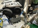
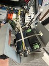
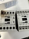
Here is the problem: I have a large format printer that has a built in chiller. A few days ago we smelled a slight burning smell coming from the machine. We could not pinpoint the issue so we let it continue to run. The next day as it was running we saw a spark from the machine and then smoke. After shutting everything down and opening it up, we found this. (see photos)
Although it just looks like a Current limiter got fried, the service tech came and informed me that they are only able to replace the entire chiller as the electronics are housed inside the chiller unit. Cost is $17k!!
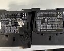
After getting past the initial shock, I let the service tech leave and I took apart the chiller unit and found the parts that were burnt. It looks like the inrush current limiter blew as you can see in the photos, it also burnt up the Contactor next to it.
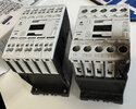
I ordered replacement parts for the three rail mounted terminal blocks, (2) inrush current limiters, and Contactor din/panel. Basically everything close to where the blown part was located.
My question is, what would have caused this? Should just replacing the parts in question be enough to fix this? Could it just be that the inrush current limiter failed due to age? The printer is in high use every day. I'm hoping that this is the case. But I thought I'd post here to see how the experts weight in and if you would do anything else differently.
Any input is greatly appreciated!
Here is the problem: I have a large format printer that has a built in chiller. A few days ago we smelled a slight burning smell coming from the machine. We could not pinpoint the issue so we let it continue to run. The next day as it was running we saw a spark from the machine and then smoke. After shutting everything down and opening it up, we found this. (see photos)
Although it just looks like a Current limiter got fried, the service tech came and informed me that they are only able to replace the entire chiller as the electronics are housed inside the chiller unit. Cost is $17k!!
After getting past the initial shock, I let the service tech leave and I took apart the chiller unit and found the parts that were burnt. It looks like the inrush current limiter blew as you can see in the photos, it also burnt up the Contactor next to it.
I ordered replacement parts for the three rail mounted terminal blocks, (2) inrush current limiters, and Contactor din/panel. Basically everything close to where the blown part was located.
My question is, what would have caused this? Should just replacing the parts in question be enough to fix this? Could it just be that the inrush current limiter failed due to age? The printer is in high use every day. I'm hoping that this is the case. But I thought I'd post here to see how the experts weight in and if you would do anything else differently.
Any input is greatly appreciated!