Continue to Site

Welcome to our site!

Electro Tech is an online community (with over 170,000 members) who enjoy talking about and building electronic circuits, projects and gadgets. To participate you need to register. Registration is free. Click here to register now.

  • Welcome to our site! Electro Tech is an online community (with over 170,000 members) who enjoy talking about and building electronic circuits, projects and gadgets. To participate you need to register. Registration is free. Click here to register now.

V to I Converter(opamp)

Status
Not open for further replies.

axro

New Member
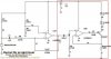
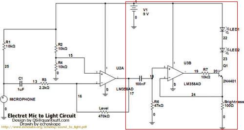
I was looking at a circuit for a color organ. The right half of the circuit(in the red square) is described as a V to I converter.

the-schematic-jpg.44692


I've looked online and can't find anything on it(useful). I find alot of stuff about I to V but not the other way around.

So I duplicated that part of a circuit in a simulator and it works and all I just don't understand the concept. Do you have to employ a transistor to get the V-I to work? I tried subtracting and adding parts and could only get it to work with a transistor.
 

Attachments

  • The-Schematic.jpg
    The-Schematic.jpg
    17.8 KB · Views: 2,175
Hi,


A V to I converter like this kind is a relatively simple idea...take a voltage and convert it to a current so that when you vary the input voltage the output current follows that variation. You dont need a transistor if the output current does not have to be higher than what the op amp can put out.
In fact, you dont even need an op amp if your load is a certain constant resistance because when you apply a voltage across a resistor a current develops.

If your V to I was 1 to 1, you would input 10mv and get 10ma output, 100mv in and 100ma out, etc., although many of these circuits use a different ratio of input to output. In your circuit, when a voltage of 1v is applied to the non inverting input terminal of the second op amp section in order to get 1v at the inverting terminal 1v would have to appear across the emitter resistor and that would mean 1/100 amps (which is 10ma) would have to flow through the emitter, and ignoring the base current (high gain transistor) the current in the collector is roughly the same and so the current in the collector is 10ma too.
Ignoring the base current means there will be a slight inaccuracy in the current setting (about 1 part in 100) but that is often good enough. In this case of driving LEDs, it should certainly be good enough. For higher accuracy however a slightly different circuit topology is employed (where the current in the collector is measured rather than in the emitter as in this circuit) making the output setting much more accurate. Sometimes the load is placed in the emitter circuit which also provides for higher accuracy.
Note also that this circuit is a current 'sink'. Placing the load in the emitter circuit would make it a current 'source', although for LEDs it doesnt matter that much.

In terms of spice or general circuit analysis, this would be called a "voltage controlled current source", or simply an "I of V" dependent source.
 
Last edited:
The second opamp has its input driven with AC that is referenced to ground. The negative swing is to a very negative voltage that causes the opamp to charge the input capacitor and to mis-function. The max recommended input voltage listed on the datasheet for the LM358 is only -0.3V.
This can be fixed if the second opamp is inverting. Then its input stays at 0V and never goes negative.

The first opamp is inverting which results in a low input resistance which loads down the mic output. The first opamp should be non-inverting so it has a fairly high input resistance.
 
Thank you very much MrAl for the great in-depth answer. I really appreciate it.

AudioGuru, I though the inverting and non-inverting both had the same high resistance?

I was curious about this circuit myself. I was wondering why you would want the input going into the 2nd opamp to be negative at all? From my simulations at least the output of opamp 2 has huge gaps in it where the input goes negative. So the led's are lighting and dimming to the whole range of the spectrum.

So would it not be better to bias the input opamp to to someting positive instead of 0?
 
Last edited:
AudioGuru, I though the inverting and non-inverting both had the same high resistance?
No.
The input resistance of a non-inverting opamp is the input bias resistor (could be 1M or higher) in parallel with the input resistance of the opamp (that could be many megohms).
The input resistance of an inverting opamp is the input resistor which is R3 in this circuit which is only 2.2k ohms which "shorts" the high resistance signal from the mic.

I was curious about this circuit myself. I was wondering why you would want the input going into the 2nd opamp to be negative at all? From my simulations at least the output of opamp 2 has huge gaps in it where the input goes negative.
The first opamp is biased at half the supply voltage by R2 and R4 so its output swings equally positive to about +7.5V max and negative to about +3V.
The second opamp is biased at 0V so that the LEDs arte turned off when there is no signal. The 100nF coupling capacitor causes the input of the second opamp to swing to +3V and to -3V.

So the led's are lighting and dimming to the whole range of the spectrum.
Yes.
The LEDs are simply driven half-wave because the second opamp circuit is a rectifier. When the sound is weak then the LEDs are dim and when the sound is loud then the LEDs are bright.

So would it not be better to bias the input opamp to to someting positive instead of 0?
It is biased positive, by R2 and R4. The 100nF coupling capacitor blocks its DC so that the second opamp can remain biased at 0V so that the LEDs dim when the sound is weak and turn off when there is no sound.
 
Last edited:
The minimum input resistance of a lousy old 741 opamp is 300 thousand ohms.
The typical input resistance of a TL081 opamp is 10 trillion ohms.

The input resistance at the inverting input of any opamp that has negative feedback is zero ohms. So the input resistance of an inverting opamp circuit is the value of its input resistor.
 
Status
Not open for further replies.

Latest threads

New Articles From Microcontroller Tips

Back
Top