Continue to Site

Welcome to our site!

Electro Tech is an online community (with over 170,000 members) who enjoy talking about and building electronic circuits, projects and gadgets. To participate you need to register. Registration is free. Click here to register now.

  • Welcome to our site! Electro Tech is an online community (with over 170,000 members) who enjoy talking about and building electronic circuits, projects and gadgets. To participate you need to register. Registration is free. Click here to register now.

using the CCP1 output/input pin 18 on an 18F1320

Status
Not open for further replies.

MrDEB

Well-Known Member
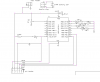
need to enable 3 outputs determined by a phototransistor Q1 and figure that the ccp1 pin 18 on an 18F1320 would do the deed unless a better method.
**broken link removed**
the photo transistor measures .03Meg with ligh and .800+Meg in dark
gots to be a better method?? and how to use the compare function or would ADC be better?
 
I have a sample of what would work but I'm just getting my shop back and running been a long road home.
Here a sample that Graham did I'll post mine when I get my shop computer put together I just got back getting the rest
of my things from kY.

Code:
Include "ADC.bas"                   // Include the ADC.bas library
 
Dim LED0 as PORTB.0                  // Declare the LED pin
Dim LED1 as PORTB.1
Dim LED2 as PORTB.2
 
function Get_ADC_Sample() as word   // Function to grab the ADC sample
 
   result = ADC.Read(0)             // Grab an ADC sample from channel 0
   result = result * 2              // Scale the answer up by a factor of 2
 
end function
 
 
OSCCON = %01110110                 // Setup the internal OSC for 8Mhz
 
Input(PORTA.0)                     // Make AN0 an input
 
[COLOR="Red"]While True                         // Create an infinate loop
 
    High(LED)                      // Make the LED pin High
    Delayms(100 + Get_ADC_Sample)  // Delay for 0.1 seconds + the ADC result
 
    Low(LED)                       // Make the LED pin Low
    Delayms(100 + Get_ADC_Sample)  // Delay for 0.1 seconds + the ADC result
 
Wend [/COLOR]
Just move the wire from RB3 to RA0
And change the part in red to the code your running for the pwm
 
Last edited:
Code but not tested

Need to experiment with the resistor voltage divider for the portA0 input to achieve "result"
Code:
Device = 18F1320
Clock = 8

Include "IntOSC8.bas" 
Include "RandGen.bas"
Include "Utils.bas"
Include "ADC.bas"                   // Include the ADC.bas library
 
Dim LED As PORTB.3                  // Declare the LED pin turns on transistor
 

//OSCCON = %01110110                 // Setup the internal OSC for 8Mhz
 

Dim TMR2IE As PIE1.1,         // TMR2 interrupt enable
    TMR2IF As PIR1.1,         // TMR2 overflow flag
    TMR2ON As T2CON.2,        // Enables TMR2 to begin incrementing
    Signal_Pin As PORTA.0     // Signal output to frequency meter
 
Dim Red_Pin As PORTB.0,
    Green_Pin As PORTB.1,
    Blue_Pin As PORTB.2,
    Red_Duty As Byte,
    Green_Duty As Byte,
    Blue_Duty As Byte,
    Red_DutyVal As Byte,
    Green_DutyVal As Byte,
    Blue_DutyVal As Byte,
    RandomVal As Byte
   
 
Dim uS As Word,
    mS As Word           
  
Interrupt TMR2_Interrupt()
    High(Signal_Pin)
    Save(0)                   // Back up system variables   
    If TMR2IF = 1 Then        // Check if the interrupt was from TMR2   
        TMR2IF = 0            // Clear the TMR2 interrupt flag
        uS = uS + 50
        If uS >= 1000 Then
            uS = uS - 1000
            Inc(mS)
        EndIf       
        Inc(Red_DutyVal)
        Inc(Green_DutyVal)
        Inc(Blue_DutyVal)
        If Red_DutyVal > Red_Duty Or Red_Duty = 0 Then
            Red_Pin = 0
        Else
            Red_Pin = 1
        EndIf
        If Green_DutyVal > Green_Duty Or Green_Duty = 0 Then
            Green_Pin = 0
        Else
            Green_Pin = 1
        EndIf
        If Blue_DutyVal > Blue_Duty Or Blue_Duty = 0 Then
            Blue_Pin = 0
        Else
            Blue_Pin = 1
        EndIf               
    EndIf                     //
    Restore                   // Restore system variables
    Low(Signal_Pin)
End Interrupt
 
Private Sub TMR2_Initialize()
    TMR2ON = 0                // Disable TMR2
    TMR2IE = 0                // Turn off TMR2 interrupts   
 
    PR2 = 149                 // TMR2 Period register PR2
    T2CON = %00000001         // T2CON 0:1 = Prescale
                              //        00 = Prescale is 1:1
                              //        01 = Prescale is 1:4
                              //        1x = Prescale is 1:16                                 
                              //      3:6 = Postscale              
                              //     0000 = 1:1 postscale
                              //     0001 = 1:2 postscale
                              //     0010 = 1:3 postscale...
                              //     1111 = 1:16 postscale
 
    TMR2 = 0                  // Reset TMR2 Value   
    TMR2IE = 1                // Enable TMR2 interrupts
    TMR2ON = 1                // Enable TMR2 to increment
    Enable(TMR2_Interrupt)
End Sub
 
// Start Of Program...
Low(Red_Pin)
Low(Green_Pin)
Low(Blue_Pin)
Red_Duty = 30
Green_Duty = 0
Blue_Duty = 0
Red_DutyVal = 0
Green_DutyVal = 0
Blue_DutyVal =0
 
uS = 0
mS = 0

RandGen.Initialize(128)       // Initialize the Random Number generator
TMR2_Initialize               // Setup and enable TMR2
 
While True                    // Create an infinite loop
    RandomVal = RandGen.Rand  // Grab a random number from 0 to 255 
   
             Red_Duty =RandomVal-25 


            If Red_Duty > 0
              Then  mS = 0
                Repeat
                Until mS = 19
                Dec(Red_Duty)
            EndIf
      
             Green_Duty =RandomVal-20 
             
            If Green_Duty > 0
              Then  mS = 0
                Repeat
                Until mS = 19
                Dec(Green_Duty)
            EndIf
     
             Blue_Duty = RandomVal-30
             
            If Blue_Duty > 0
              Then  mS = 0
                Repeat
                Until mS = 19
                Dec(Blue_Duty)
            EndIf
            Wend
          
         End 
 Function Get_ADC_Sample() As Word   // Function to grab the ADC sample
 
   result = ADC.Read(0)             // Grab an ADC sample from channel 0
   result = result * 2              // Scale the answer up by a factor of 3
 
End Function
 
 
OSCCON = %01110110                 // Setup the internal OSC for 8Mhz


Input(PORTA.0)                     // Make AN0 an input


While True                         // Create an infinate loop
 
    High(LED)                      // Make the LED pin High
    DelayMS(100 + Get_ADC_Sample)  // Delay for 0.1 seconds + the ADC result
 
    Low(LED)                       // Make the LED pin Low
    DelayMS(100 + Get_ADC_Sample)  // Delay for 0.1 seconds + the ADC result
 
Wend 
 // need to change so result < ? then (led) high turns on transistor for windows
 
My proposed schematic

With light I get ,8v without light I get 2.++ volts
it varies but a wide range it seems. led candles3_30_1&#4.PNG
BUT it dosn't look right? not electrically sound but ???
Don't know if I could just ENABLE the B ports and eliminate the transistor?
 
Are you just trying to detect light and dark? If so, I was able to do something like that just using a plain vanilla LED. If you're interested I will look for my notes... I think it was just a matter of charging it up and then switching to an input and measuring the discharge time (which is affected my the amount of light on the LED)...

Mike
 
Last edited:
I am detecting light and dark in a room. The room may be dark for several days so a discharging circuit may not work
This is similar to a CDS / voltage comparator circuit in that it performs the same task.
In darl condition, the window LEDs are ON using PWM.
In daylight, the window LEDs are OFF.
All this is controlled using a PIC (see schematic)
 
Well it's not a "discharging circuit" but rather a method that charges the diodes PN junction by reverse biasing the diode and then counting how long it takes for that junction to discharge. If interested, here's a thread that you might check out LED as Ambient Light Sensor & Indicator.

Regards, Mike
 
This is a pretty cool idea. I think I remember Forrest Mims talking about this in one of his books, using different color LEDs on satellites to measure tree density.
 
I may need to rewrite the ADC code slightly as I can't get the LED connected to port B0 to turn on. I need to add an >= formula but running out of time.
Still need to either etch a pc board or hard wire circuit. Contemplating taking the easy route and use a 741 op amp comparator circuit (easy way out. Yea I know it sounds like I am giving up but ???
 
still hacking away at this simple code

syntax error. I figure if result >= 1 then the LED(0) should be high
Code:
Include "ADC.bas"                   // Include the ADC.bas library
 
Dim LED0 As PORTB.0                  // Declare the LED pin
Dim LED1 As PORTB.1
Dim LED2 As PORTB.2
 
Function Get_ADC_Sample() As Word   // Function to grab the ADC sample
 
   result = ADC.Read(0)             // Grab an ADC sample from channel 0
   result = result * 2              // Scale the answer up by a factor of 2
 
End Function
 
 
OSCCON = %01110110                 // Setup the internal OSC for 8Mhz
 
Input(PORTA.0)  // Make AN0 an input
 
While True                         // Create an infinate loop
 result >= 1
 high (LED0)   
  
 
 wend
 
MeDeb the result is a lot more then 1 if the photo transistor is on it's a 10 bit number so you want to compare it to a lager number
like
Code:
If result > 128 Then 
   high (LED0)
Endif
 wend
If you just compared to 1 it would never go off I think it's right justified in the module so
you could say 0 volts is 0 and full on is 256
 
Last edited:
this is what I put into Junebug

using the VR1 pot (10k) as input to RA1
output is port a.0
will increase number but how to do an >= so I have a larger range or ?
Code:
Include "ADC.bas"                   // Include the ADC.bas library
 
Dim LED0 As PORTa.0                  // Declare the LED pin
//Dim LED1 As PORTB.1
Dim LED2 As PORTa.6
dim Aresult as word 
Function Get_ADC_Sample() As Word   // Function to grab the ADC sample
 
   Aresult = ADC.Read(0)             // Grab an ADC sample from channel 0
  Aresult =Aresult * 2              // Scale the answer up by a factor of 2
 
End Function
 
 
OSCCON = %01110110                 // Setup the internal OSC for 8Mhz
 
Input(PORTA.0)  // Make AN0 an input
 porta.6=0
While True                         // Create an infinate loop
 Aresult = 1  //[COLOR="Red"]??? increase to ??[/COLOR]
 high (LED0)   
  
 
 wend
 
warning warning! Will Robinson!

changed as per suggestion but I get a warning
Code:
Include "ADC.bas"                   // Include the ADC.bas library
 
Dim LED0 As PORTa.0                  // Declare the LED pin
//Dim LED1 As PORTB.1
Dim LED2 As PORTa.6
dim Aresult as word 
Function Get_ADC_Sample() As Word   // Function to grab the ADC sample
 
   Aresult = ADC.Read(0)             // Grab an ADC sample from channel 0
  Aresult =Aresult * 2              // Scale the answer up by a factor of 2
 
End Function
 
 
OSCCON = %01110110                 // Setup the internal OSC for 8Mhz
 
Input(PORTA.0)  // Make AN0 an input
 porta.6=0
While True                         // Create an infinate loop
If Aresult > 128 Then 
   high (LED0)
Endif
 wend
 
I tried changing the ADC.READ(0) TO ADC.read(1)
still not working.
Bt adjusting VR1 (RA1) it should out an analoge signal to convert??
 
Here try this
Code:
Include "ADC.bas"                   // Include the ADC.bas library [COLOR="Red"] you had this  / Include "ADC.bas" didn't need the backslash [/COLOR]
 
Dim LED0 As PORTa.0                  // Declare the LED pin
//Dim LED1 As PORTB.1
Dim LED2 As PORTa.6
dim Aresult as word 
Function Get_ADC_Sample() As Word   // Function to grab the ADC sample
 
   Aresult = ADC.Read(0)             // Grab an ADC sample from channel 0
  Aresult =Aresult * 2              // Scale the answer up by a factor of 2
 
End Function
 
 
OSCCON = %01110110                 // Setup the internal OSC for 8Mhz
 
Input(PORTA.0)  // Make AN0 an input
 porta.6=0
[COLOR="Red"] Aresult =0     // clears Aresults [/COLOR]
While True                         // Create an infinate loop
If Aresult > 128 Then 
   high (LED0)
Endif
 wend
 
Last edited:
Copied and pasted. Just need to program little Junie and give it a whirl
sure glad Toyota didn't make the Junebug or it might run away
 
my bad but still doesn't work
Needed to turn vr1 and vr2 on using the dip switches.
am still wondering if the charliplexing is fouling this up.
 
If I get time I'll see if i can try this out to nite on my junebug and see what happens I haven't had much time lately
It a lot of work being a mom and a dad to twins.
 
Here is my testing schematic

I just may use this to insert into the project.
Using this to eliminate ANY chariplexing issues or other ??
 

Attachments

  • testing pcb..PNG
    testing pcb..PNG
    31.4 KB · Views: 168
Status
Not open for further replies.

Latest threads

New Articles From Microcontroller Tips

Back
Top