Continue to Site

Welcome to our site!

Electro Tech is an online community (with over 170,000 members) who enjoy talking about and building electronic circuits, projects and gadgets. To participate you need to register. Registration is free. Click here to register now.

  • Welcome to our site! Electro Tech is an online community (with over 170,000 members) who enjoy talking about and building electronic circuits, projects and gadgets. To participate you need to register. Registration is free. Click here to register now.

using PWM to dim LED NEON STRIP

MrDEB

Well-Known Member
couldn't locate this thread but here is the issue
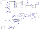
I breadboarded this circuit and it seems to work driving just an LED but I am driving a 12v led neon strip.
The circuit flashes the strip slowly to fast as per pot adjustment.
The 555 circuit works as planned with one LED (it is supposed to change the duty cycle
Thinking the two different supply voltages has something but what to do? Any suggestions?
NOTE THE 7555 IS POWERED BY THE pic
the MOSFET is logic level
 

Attachments

  • dimming circuit brd.png
    dimming circuit brd.png
    89.4 KB · Views: 373
According to TIs datasheet for the LM555...
Silly me, I used the datasheets for the ICM7555 and RFP12N10L shown on the schematic.
That's a min of 4V (typ 4.5V) output, which looks to be good for about 15A+.

My bad. It'll probably end up with some random set of parts anyway.
 
While simulating in easyeda it occurred to me, why not just insert a 9 volt regulator to power all the 555;s instead of using a zener on each 555 timer
one regulator instead of 3+ zeners.
 
You use 1K ohm in series with gate, so MOSFET is taking lots of time transitioning thru linear
region of Vds >> 0, so lots of Pdiss. You might consider more like 50-100 ohms would be
adequate. That does mean switching now faster, so more EMI and more current flowing
in board ground paths, so "stiff" ground path important. And supply bypassing.

Bulk bypass caps, lower esr = better :

1689786105173.png


OS-CON is polymer tantalums

If you have a DSO use on infinite persistence and look at supply rail noise versus bypass
cap you try. Also for gate R use DSO to look at transient to try various R value to optimize.
The R will dampen this type of tranient due to to stray L and package L.

1689786450482.png


Regards, Dana.
 
Last edited:
All I have is a DMM. DSO??
I am contemplating going back to the irf520 Mosfets with lower Rds resistance and using a gate driver like NCP81074A
I need to research. Reason for going to logic level Mosfet, it was suggested but after further research, I find it has numerous trade-offs like higher Rds. Will maybe use the logic level Mosfets for the dimming sections
 
MrDEB, you certainly do like to over-complicate projects with components you don't understand.....

IIFC (geez, a lot of your junk is taking up space in my brain), none of your strings of LEDs or LED strips draw more than 500mA (this is something you NEED to know to evaluate any switching solution). If this is in fact true, you can stop collecting mosfets that aren't right for the task, and use a ULN2003A 7 channel peripheral driver or an 8 channel ULN2803A version. Each of the 7 (or 8) channels will handle 500mA and driving them with 5 volt logic is not a problem. For about 50 cents, you've got 7 channels covered.

The base resistors are built in, so this chip eliminates a lot of the clutter you've included. The LED series resistors are already built into the LED strips, so they would not be needed (with the strips) as shown below.

anschluss-ohmscher-lasten-unl2003.jpg&quality=100.jpg
 
All I have is a DMM. DSO??
I am contemplating going back to the irf520 Mosfets with lower Rds resistance and using a gate driver like NCP81074A
I need to research. Reason for going to logic level Mosfet, it was suggested but after further research, I find it has numerous trade-offs like higher Rds. Will maybe use the logic level Mosfets for the dimming sections

DSO = Digital storage oscilloscope

Logic level MOSFETs and Rdson :


Regards, Dana.
 
Last edited:
will consider the ULN2003 but some of the strips will draw more than 500ma. I mentioned that I want to keep the strips to draw no more than 2amps. 2amps max. A 16.4 ft led strip draws 4 amps (.8A/meter at 12v. 9.6Watts per meter.)
 
I mentioned that I want to keep the strips to draw no more than 2amps. 2amps max.

Sorry I can't keep the details straight when you've mixed details among at least 4 different threads each with many pages as you alter course repeatedly.

If the strips draw more than 500mA, this isn't a solution.
 
A little out of touch guys. "LED neon" is like an LED strip with closely-spaced LEDs, oriented to fire sideways in a molded translucent plastic casing. Looking "front on", with the closely spaced side-firing LEDs, the look is very close to a neon tube.
 
71sE4tqPYTL._AC_SL1500_.jpg
 
been considering just using a 555/dimming circuit on all the Mosfet outputs and going with a standard IRL520 Mosfet.
This would add to the versatility of the PC board. More details to follow
 
If you want to drop all the 555's, use the uC to do software PWM, and use the 3 pots to set the PWM outputs, here's some code that should do that
Code:
// Swordfish BASIC three channel software PWM using TMR2 and ADC inputs
device = 18F2221
clock = 32

include "intosc.bas"
// do NOT include setdigitalio
// to use PORTB for the ADC all pins must be in analog mode due to the way
// these old pics map ADC inputs

include "adc.bas"

// ADC pot inputs
// used to set the PWM duty cycle for PWM1-PWM3
// connect pot upper lug = VDD, lower lug = GND, wiper = port IO
dim
    POT1 as PORTB.0,    // RB0/AN12
    POT2 as PORTB.1,    // RB1/AN10
    POT3 as PORTB.2     // RB2/AN8

// ADC channels
const
    CH_POT1 = 12,       // AN12
    CH_POT2 = 10,       // AN10
    CH_POT3 = 8         // AN8
 
// PWM outputs
dim
    PWM1 as PORTA.5,
    PWM2 as PORTA.6,
    PWM3 as PORTA.7

// pwm duty cycles (from ADC) 0=min, 255=max
dim
    pwm1_duty as byte,
    pwm2_duty as byte,
    pwm3_duty as byte

dim pwm_period as byte

// pwm timer TMR2
dim
    TMR2IF as PIR1.bits(1),
    TMR2IE as PIE1.bits(1),
    TMR2ON as T2CON.bits(2)
 
// set IO pin directions and initial settings
sub InitIO()
    // set inputs
    input(POT1)
    input(POT2)
    input(POT3)
 
    // set outputs (low to start)
    low(PWM1)
    low(PWM2)
    low(PWM3)
end sub

// pwm TMR2 interrupt
interrupt tmr2_isr()
    TMR2IF = 0   
    pwm_period = pwm_period + 1
    if (pwm_period >= pwm1_duty) then
        PWM1 = 0
    else
        PWM1 = 1
    endif
    if (pwm_period >= pwm2_duty) then
        PWM2 = 1
    else
        PWM2 = 0
    endif
    if (pwm_period >= pwm3_duty) then
        PWM3 = 1
    else
        PWM3 = 0
    endif
end interrupt


main:
InitIO()

// ADC setup
ADCON1 = $00        // all pins set to analog mode, VREF = VDD/GND
ADCON2 = ADC.FRC    // ADC clock = Frc
ADC.ADFM = 0        // left justify (we only use the 8 MSB's)
ADC.SetAcqTime(100) // 100us delay

pwm_period = 0
pwm1_duty = 0
pwm2_duty = 0
pwm3_duty = 0

// setup pwm timer TMR2
// 25KHz = 40us/bit -> 40us x 256 = 10240us period, ~10ms period (100Hz)
T2CON = %00000001   // T2OUTPS<3:0>=%000 (1:1), TMR2ON=0, T2CKPS<1:0>=%01 (1:4)
PR2 = 176
TMR2 = 0
TMR2IF = 0
TMR2IE = 1
TMR2ON = 1

enable(tmr2_isr)

while (true)
    pwm1_duty = ADC.Read(CH_POT1) >> 8
    pwm2_duty = ADC.Read(CH_POT2) >> 8
    pwm3_duty = ADC.Read(CH_POT3) >> 8
end while

I picked pins that were somewhat close to what you have now, but you do have to rearrange some stuff to get the pots connected to ADC pins. You may have trouble using a 50K pot (5K would be better), but try adding a small cap to GND on the ADC input pins... 0.01uF or 0.1uF should work.

Code's completely untested but it should be close...

EDIT: this should give you pretty close to 5V gate drive, so it should work with either mosfet you've been looking at. Be sure to reduce the value of the 1K resistors you have on the gate... 100ohms (or less).
Keep the 10K gate pulldown so the mosfets don't turn on before everything starts up.
 
Last edited:
THANKS have a test board assembled and will give it a try.
One drawback if using a Logic level, the Rds(on) is higher than a standard mosfet.
 

New Articles From Microcontroller Tips

Back
Top