Continue to Site

Welcome to our site!

Electro Tech is an online community (with over 170,000 members) who enjoy talking about and building electronic circuits, projects and gadgets. To participate you need to register. Registration is free. Click here to register now.

  • Welcome to our site! Electro Tech is an online community (with over 170,000 members) who enjoy talking about and building electronic circuits, projects and gadgets. To participate you need to register. Registration is free. Click here to register now.

using PWM to dim LED NEON STRIP

MrDEB

Well-Known Member
couldn't locate this thread but here is the issue
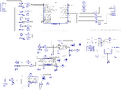
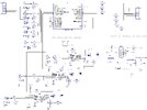
I breadboarded this circuit and it seems to work driving just an LED but I am driving a 12v led neon strip.
The circuit flashes the strip slowly to fast as per pot adjustment.
The 555 circuit works as planned with one LED (it is supposed to change the duty cycle
Thinking the two different supply voltages has something but what to do? Any suggestions?
NOTE THE 7555 IS POWERED BY THE pic
the MOSFET is logic level
 

Attachments

  • dimming circuit brd.png
    dimming circuit brd.png
    89.4 KB · Views: 375
If the goal is just to control the overall brightness of all of the strips, all the falderal could be replaced with an AND gate in front of each MOSFET. One of the inputs goes to the controlling port pin. The other input of all of the AND gates goes to a PWM pin. THE PWM output (i.e., ONE, SUNGULAR) controls the brightness of all of the strips. The other input controls whether each strip is on.

I really tried my best to explain this concept as completely as possible when I posted it.

The ONE PWM output controls the overall brightness of ALL of the strips, which WILL BE THE SAME FOR ALL OF THE STRIPS.


Arrrggghhhh.jpg
[/b]
 
Here is a truth table for an AND gate, just to cover 100% of the concept I presented. A and B are inputs. Y is the output.

SmartSelect_20230715_115946_Edge.jpg


One when both inputs are HIGH is the output HIGH. If the "control" input is LOW and the PWM input has a square wave, the output will always be off.

If the "control" input is high and the PWM input is active, the output will follow the PWM signal.
 
I wanted to be able to adjust each strip individually.
I simulated Jverive suggestion (post#16) and IF I can alter my pc boards without having to reorder, this idea of controlling the 555 timer with the RESET pin looks promising.
One thing, the RESET pin goes high the MOSFET GATE looks like 10.6 volts. The data sheet says Vgs= 10v +/-
Does this mean I shouldn't exceed 10 volts on the gate?
 
[
I wanted to be able to adjust each strip individually.


If the goal is just to control the overall brightness of all of the strips......

My intent was made perfectly clear in my post. Sorry this and every other point I made was unclear to you. I typed as slowly as I could!
 
If you wanted to use hdw PWM you'd have to use a different PIC... the 18F2221 only has 2 CCP/PWM peripherals.

Of course, pretty much every single thread MrDEB's involved with has used some form of software PWM, and we're only on pg 2. It'd be easy to use a timer and generate three PWM outputs.
 
I wanted to be able to adjust each strip individually.
I simulated Jverive suggestion (post#16) and IF I can alter my pc boards without having to reorder, this idea of controlling the 555 timer with the RESET pin looks promising.
One thing, the RESET pin goes high the MOSFET GATE looks like 10.6 volts. The data sheet says Vgs= 10v +/-
Does this mean I shouldn't exceed 10 volts on the gate?

Vgs max :

1689601715246.png


The 10V value you are referring to is a spec for Rdson :

1689601789897.png


Regards, Dana.
 
Reason I am using 18f221 is I have about 10 of them on hand.
It was mentioned to use a timer and get 3 PWM outputs. Hom many are pissable?
QUESTION?? What is wrong with using the 555 timer?
I need to invistiagte post#29
 
Am confused as the datasheet for the RFP12N10L states a maximum rating of Vgs is +-10
yet post#29 shows -30 to 30 volts
EXPLAIN WOULD HELP
 
Post # 29 was for 2N7002, from post #22

Regards, Dana.

Sorry I caused some confusion. I showed 2N7002s in a concept starting in post #18. Considering that nearly every point in the six sentences describing the concept were overlooked, I eventually added this disclaimer in a following post.

Note, power and ground connections and a 100nF bypass cap are not shown in the schematic. MOSFET part numbers are representative only and are NOT a recommendation.
 
it was mentioned to use a timer and get 3 PWM outputs. Hom many are pissable?
In this thread they're all pissable. The number of possible timers is the number of IO pins you have.
Probably the less you have, the simpler it is to write the code.

QUESTION?? What is wrong with using the 555 timer?
QUESTION? what the hell is the micro doing other than just sitting there?
You've almost added more circuitry with the 555's than the entire rest of the board.
 
Here is the revised schematic with the pic controlling the 555 timers for dimming of led strips
All the MOSFETs connected to portA are used for other led strips. For example from the picture in post#12 the green strips each have their own port controlling them. PortC.0 - portC.6 control single green leds that are located in the straw to simulate "sipping" on the straw. The frosted blue (the glass) is going to be dimmed as will the red straw
 

Attachments

  • SIGN PCB BRD7_18_23.jpg
    SIGN PCB BRD7_18_23.jpg
    537.6 KB · Views: 95
You forgot the zener diodes to clamp the gate voltage to 10V max.

Better yet, why are you running the 555's at 12V?
Just run them at 5V with everything else and then you won't have to bother with the zener.
You're using logic-level mosfets so the output of the 555's @ 5V should be fine.
 
You forgot the zener diodes to clamp the gate voltage to 10V max.

Better yet, why are you running the 555's at 12V?
Just run them at 5V with everything else and then you won't have to bother with the zener.
You're using logic-level mosfets so the output of the 555's @ 5V should be fine.
According to TIs datasheet for the LM555, the typical output when Vcc is 5 Volts is only 3.3 Volts, which is probably not enough to fully turn the mosfet on.
 

New Articles From Microcontroller Tips

Back
Top