KeepItSimpleStupid You asked about the connectors so that I can connect my USB devices right? Or was there any other reason.
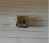
I have these handy. I have got 3 of such connectors. One for the USB keyboard and the other two for the two PCs. I also have two USB to USB wires so that I connect them to the PCs.
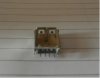
At first, I will try to switch the keyboard and then if successful I will switch the mouse as well by buying another 4PDT switch.
I have these handy. I have got 3 of such connectors. One for the USB keyboard and the other two for the two PCs. I also have two USB to USB wires so that I connect them to the PCs.
At first, I will try to switch the keyboard and then if successful I will switch the mouse as well by buying another 4PDT switch.
")
