Continue to Site

Welcome to our site!

Electro Tech is an online community (with over 170,000 members) who enjoy talking about and building electronic circuits, projects and gadgets. To participate you need to register. Registration is free. Click here to register now.

  • Welcome to our site! Electro Tech is an online community (with over 170,000 members) who enjoy talking about and building electronic circuits, projects and gadgets. To participate you need to register. Registration is free. Click here to register now.

TL072 and Non-inverter small signal amplifying

arvinfx

Member
Hi,
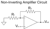
I have 80mVpp 100hz sinusoidal, I have to amplify it to 2Vpp . With -7 +7 opamp power supply. I have made blow circuit :

Untitled-1.jpg


It works, But I cause distortion in Vin !!! If I change 70K resistor to 40K distortion will solve 100%!

My question is : Do we have effect on +in pin when we use Non-inverter opamp design ? if yes what we have to do to prevent it ?

Master amplifier schematic:

Datasheet
 

Attachments

  • images.png
    images.png
    4.7 KB · Views: 72
Last edited:
First, the power supply.
The TL072 is not a "rail-to-rail" output device.
The maximum positive output will be "power supply minus 1.5 volts" at best.
The minimum output will be 1.5 volts above the Vcc- (negative supply to the op amp).

In other words, it is best (easiest) to power this device with a bi-polar supply ( e.g. -15, and +15v). The 0V "ground" would be the triangle in your schematic. Again, this means, the triangle in the schematic should NOT be connected to pin #4 of the TL072.

Second
Your sinousoidal input should not be capacitively coupled to the non-inverting input (even if you send the signal through the unnecessary 68ohm resistor. You are creating a current trap of sorts since the non-inverting input has such a high input resistance as it is a jfet device. To overcome this, you can try adding a 10k to 1M resistor from your non-inverting input to the ground (not the Vcc- supply but the triangle ground symbol in your schematic).

Look at the datasheet. Also, the TL072 has evolved - the current version is TL072H. Make sure you look at the part of the TL072 datasheet for your specific device version. The input and output ranges are slightly different.

Sorry I haven't mention supply voltage it is -7 +7 volts on pin 4 and 8.
 
Last edited:
Show or describe distortion accurately.
Gain R ratio is incorrect as given for 2V/80mV

I see no problems with correct R values or even 70k
 
So what are you trying to do?, and why don't you post the complete circuit - so far you've only posted a small theoretical diagram (the sort of thing you get in text books) which is missing most of the parts that actually make it work.
 
The TL072 doesn't like driving lower impedance loads. As the load draws more and more current from the TL072 output, the difference between the Vcc and max output peaks of the amplified signal.

Per the datasheet...
A load of 10k ohms will cause a difference of 1.5-2.0v
And a load of 2k ohms can drop out up to 5v
Dropout will be more for lower resistance levels. If you can, try measuring resistance across you car amplifier's inputs. It should be more than 10k but who knws?

Also, you should have a 0.1uF cap connecting pins 8 and 4 on your TL072. Your peaks can be clipped or show small distorted spikes without it.
 
So what are you trying to do?, and why don't you post the complete circuit - so far you've only posted a small theoretical diagram (the sort of thing you get in text books) which is missing most of the parts that actually make it work.
I am trying to couple two amplifiers together without and phase shift in outputs . one of them is master and other is slave amplifier . From Master 80mVpp comes and go to TL072 and output of TL072 goes to Slave amplifier.

I don't have two amplifiers schematic. only TL072 is my design .
Also I only have one question that is mention on first post which is general question about Non-inverter opamps.

Thanks about your participate.
 
There should be no problem with +/-7V. But the real problem is your lack of details on distortion.

Perhaps you have a large common mode interference or current limiting yet to be measured or defined..
 
+/-4V min is necessary

4 R Diff mode is better for reducing possible gnd. noise gain with CMRR of R tolerances. R1 uses max current avail. with 1Vp

1706480903648.png
 
Jfets has a tiny capacitor in its gates. I thought its better to have an small resistor to prevent inrush current and further damage to source of input signal ...
Small resistors do nothing to protect high impedance inputs. It's like they ate not even there.
 
Also, you should have a 0.1uF cap connecting pins 8 and 4 on your TL072. Your peaks can be clipped or show small distorted spikes without it.
It has 47uf electrolytic capacitors on both + and -
If you can, try measuring resistance across you car amplifier's inputs. It should be more than 10k but who knws?
It is 98k assume 100k
 
It is my circuit schematic

Untitled-1.png


I have distortion problem in Audio_R1 and Audio_L1 when I turn the double volume which is To_back_vol_R more than ~70K .

Why output of this opamp affect on input of it ?!
 
Jfets has a tiny capacitor in its gates. I thought its better to have an small resistor to prevent inrush current and further damage to source of input signal ...
The input C of OpAmp inputs quite small, and a small amount added due to stray C due to layout.
No need for the 68 ohm R's.

Your G thru OpAmp is 1 + Rvol_control (K) / 2.2K. Any chance at extreme end of volume control
it goes open, very high Z. Which would cause severe distortion. Same could happen on the 0 ohm
end if real cheap pot. If thats problem obviously get quality pots, or use an additional fixed R from
output to OpAmp inv input to set max gain.

As Tony mentions regarding output load its way to low for this OpAmp, look at the datasheet charts
load current versus output swing. Its obvious your load way to large (= Rload way too small).

Laslty note you have to handle load dump in vehicle, eg. excess V, to keep from frying components.
Like bypass caps, semiconductor in general.


Notice the effect of a 50 ohm versus 1K ohm load on output :

1706535005721.png


Feedback Rfeedback of 140K, clipping evry evident :

1706535641746.png


Regards, Dana.
 
Last edited:

Latest threads

New Articles From Microcontroller Tips

Back
Top