Continue to Site

Welcome to our site!

Electro Tech is an online community (with over 170,000 members) who enjoy talking about and building electronic circuits, projects and gadgets. To participate you need to register. Registration is free. Click here to register now.

  • Welcome to our site! Electro Tech is an online community (with over 170,000 members) who enjoy talking about and building electronic circuits, projects and gadgets. To participate you need to register. Registration is free. Click here to register now.

Time delay for 12V motor using 555 IC

Status
Not open for further replies.
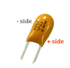
Row 11 is "-", or ground. Moving the cap lead there shorts it and, basically, removes it from the circuit. The cap's lead needs to be in either row 12 or 13.

Also, might be time for a new battery.

And, again, forget the diode for now. You're worrying this death.


I moved it to row 13 the pin in between the small red lead and the other capacitor. however it does not work and the motor just runs atw until i off the motors. the time delay didnt work

But when i moved it back to row 11 the time delay worked but its around 19secs.

haha that diode scared me for that moment because everything was working fine until i tried w the diode and it suddenly does not work anymore. but ofc i would like it to have a fixed delay
 
At this stage, I can't see enough of how the components, especially the timing caps which are polarized (+ and - leads), are arranged and if any of the leads are shorted together.

Best thing I can suggest is to pull ALL the parts off the board and remake the circuit in a new location on the board (the little lead grippers in the holes can weaken and not make contact properly).

I'd also suggest that as you build it, look at the schematic I gave you and, component by component, compare what you see on the board against that schematic. This exercise will help you a great deal in understanding the relationship of the real circuit and the schematic.

i believe that the negative terminals of the caps are those with the shorter leads and thus i connected those with the shorter ones to the negative sides of the board.
However, if i decide to keep the timeout timing at around 19 secs. As this is what i have now, how do i make use of the diode to keep its consistency going forward?
 
i believe that the negative terminals of the caps are those with the shorter leads
Do not rely on lead length for polarity.
Both caps should have a clearly printed "-" or "+" leg. The orange cap type ordinarily has the positive leg marked with a "+" sign and the round black cap types usually have the negative leg marked with a "-" sign.

The 19 second timing makes zero sense given the stated values for the timing components. Either they have significantly changed or some part of the circuit in mis-wired.

One more time. FORGET the diode for now. Get the circuit working correctly first.

For the 0.01uf capacitor , it does not indicate any + or - signs on the cap. and both of the lead length seems the same. theres only 103 and k1k written on it.

I dont know how am i getting that timing, however when i tested the circuit using a pulse generator like machine it shows that the time delay was 26 seconds however when connected to the motor it does not give such values.
 
I dont know how am i getting that timing, however when i tested the circuit using a pulse generator like machine it shows that the time delay was 26 seconds however when connected to the motor it does not give such values.
I have no idea what you're talking about.
 
I have no idea what you're talking about.

Like this type of machine. I connected it to the ground and the output of the 555 IC and when i on the switch (the one on my circuit), the graphs begins to spike and was constant for 26secs before it fell. Thn i checked the timing of the graph it shows that it lasted for 26secs before it stopped. However, i dont know why when tested with the motor plugged in it gives me 19secs delay.
tektronix-pulse-rise.jpg
 
I dont know what is happening to my circuit , i put back to its original positions and now each time i on the switch it lasts less than a sec and it turns off.

I tried moving the whole circuit to use different points too still having the same problem
 
Last edited:
What is the value of the resistor connecting pin 7 of the 555 to the +ve rail? I can't make out the band colours.

Edit:
If the timed period is less than 1 sec then the 470uF cap may not be making good contact with the breadboard sockets. Wires should enter the sockets vertically.
 
Last edited:
What is the value of the resistor connecting pin 7 of the 555 to the +ve rail? I can't make out the band colours.

Edit:
If the timed period is less than 1 sec then the 470uF cap may not be making good contact with the breadboard sockets. Wires should enter the sockets vertically.


51k resistor
I tried it again and it still is giving me less than 1sec time outs
 
A Tantalum with reverse polarity connection on the trigger pin 2?

The other on pin 5 looks to be ceramic.
 
If you ever connected the electrolytic capacitors with the wrong polarity then they may have lost capacitance. That could account for the short time-out. Try a different capacitor, ensuring the polarity is correct.
 
If you ever connected the electrolytic capacitors with the wrong polarity then they may have lost capacitance. That could account for the short time-out. Try a different capacitor, ensuring the polarity is correct.

May i ask that for a 0.01uf capacitor, how do i see its polarity as the leads seems to be off the same length. and also on the capacitor itself , it does not show and + or - signs. It just shows 103 on one side and k1k on the other
 
That Tantalum is a bit off printed,
 

Attachments

  • tantalum-capacitor.png
    tantalum-capacitor.png
    54.8 KB · Views: 190
  • - in + Row.png
    - in + Row.png
    318.8 KB · Views: 194
The 10 nano Tantalum, (0.01 uF) - lead is in the positive rails connection point and the Tantalum + lead is at pin 2 of the 555 timer. The pellet can fuse into a short when the part is powered with reverse polarity. If the pellet is fused internally that can make the trigger function act un predictable when operating in connection with the timer.
 
Or the Tantalum in reverse polarity will act as a bounce back (reject charge) when the tantalum tries to fail (pellet fusing to short). The part really can load down a circuits power supply before they make a puff. Be careful with Tantalum, their physical form can produce a volcano effect of hot gasses when they fail on a supply with plenty of current! However with a 9 V supply, the current is not known on what amount of time required to fuse the Tantalum pellet if polarity has in fact been reversed. The part would read a short if tested with a multi meter in resistance mode, or Capacitor check mode (if available) would show no charging of the capacitor at all when completely failed.

Low current, fused pellet, high current.... = some impressive effects.
 
Status
Not open for further replies.

Latest threads

Back
Top