Continue to Site

Welcome to our site!

Electro Tech is an online community (with over 170,000 members) who enjoy talking about and building electronic circuits, projects and gadgets. To participate you need to register. Registration is free. Click here to register now.

  • Welcome to our site! Electro Tech is an online community (with over 170,000 members) who enjoy talking about and building electronic circuits, projects and gadgets. To participate you need to register. Registration is free. Click here to register now.

The problem of the error light staying on in the dc to ac inverter 500w⁉️

electronium

Member
۲۰۲۴۰۲۲۵_۱۰۰۰۴۷_3f2d.jpg


۲۰۲۴۰۲۲۳_۱۳۲۷۰۵_and7.jpg

photo_2024-02-25_10-42-21_kd6u.jpg

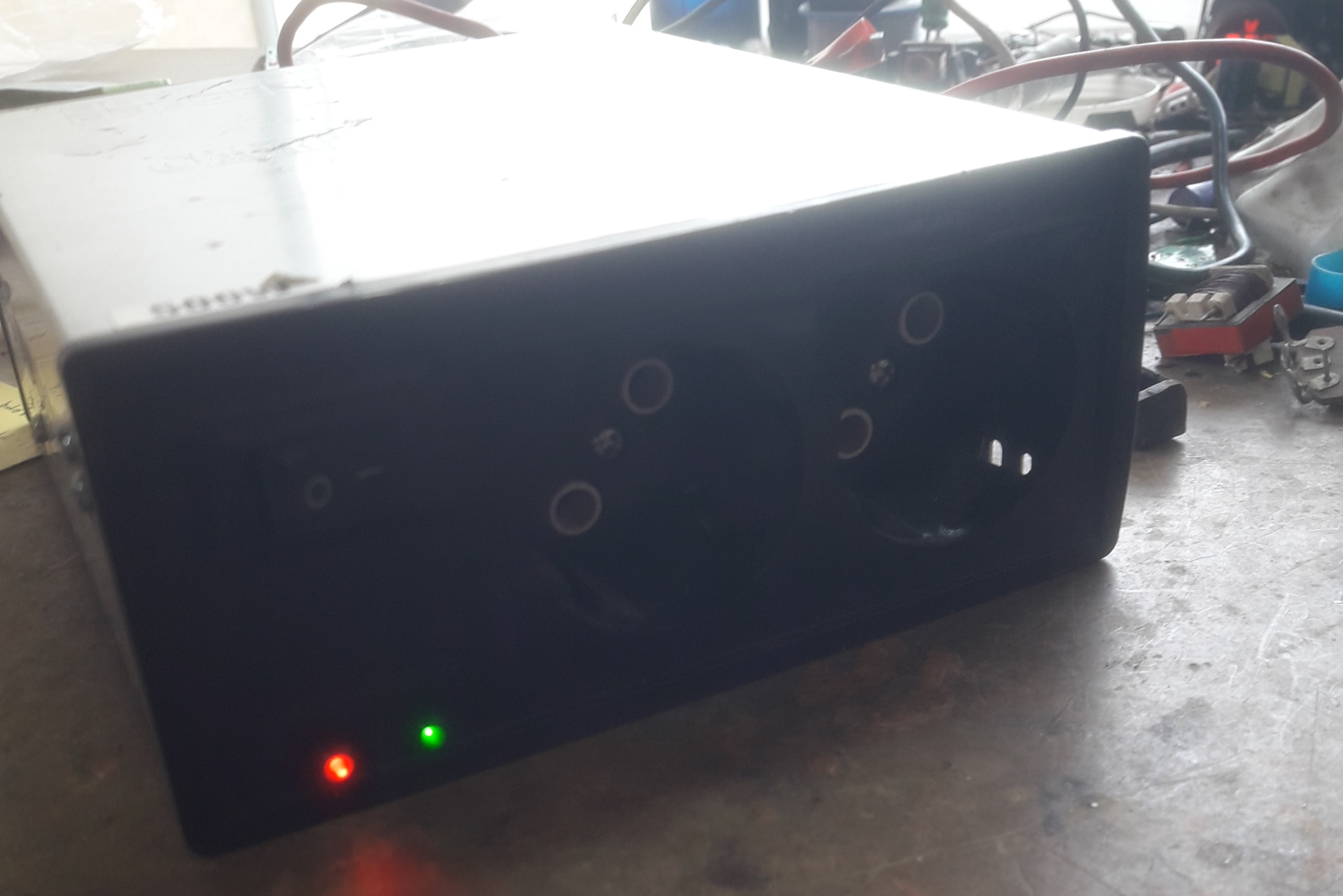
A customer brought a 500w dc/ac inverter and when I turn it on, the red error light stays on...
Operations performed:
It is in the following order
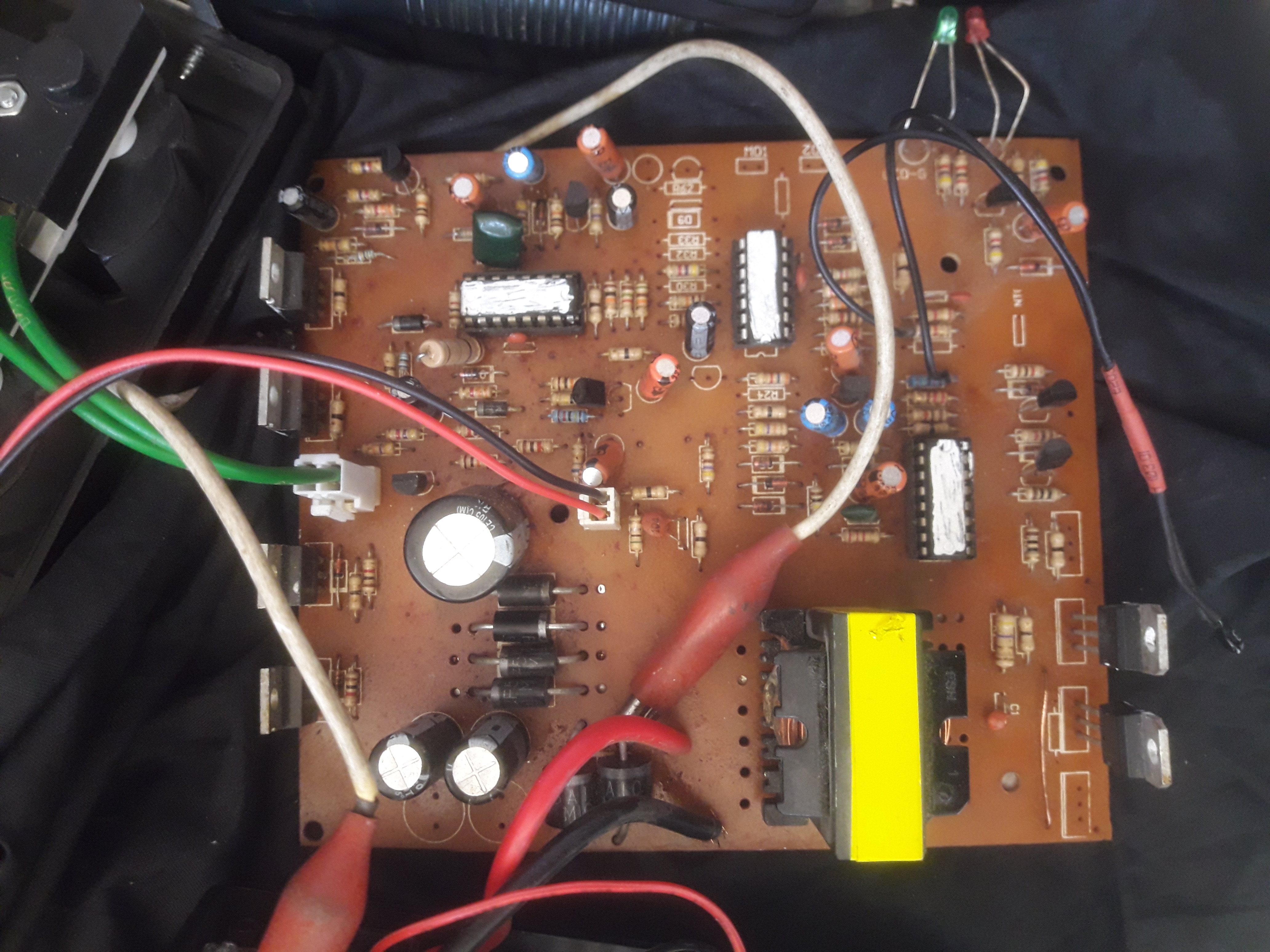
1 Testing and checking the input and output MOSFETs that are Healthy
2 Testing and checking all types of pulse and buffer transistors that are Healthy
3 Testing and checking all types of zener and signal diodes that are Healthy
4 Testing and checking all types of oscillator capacitors
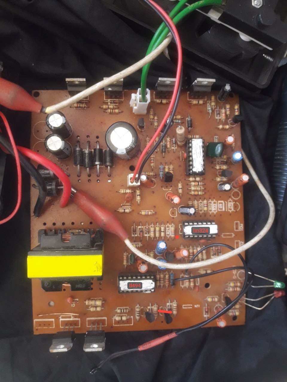
5 testing and checking ICs, except for the top one, I don't know what the part number is
 
Last edited:
Unfortunately, I don't have a scope, but I do have a multimeter
I don't know what the upper IC is, but I found out by routing by pcb, but the ground is connected to pin 9 and 10
 
Last edited:
Welcome to ETO.
Without a scope it would be extremely difficult to test all the semiconductors fully. A multimeter likely won't, for example, indicate transistor junction breakdown conditions.
Your image files need to be uploaded to this site. We can't see what's on your computer.
 
electronium is that white ink on the chips or did you edit the image to add the white areas over the chips?

Are you able to read the manufacturer name and date codes under the link?

Greetings engineer... have a good time
I would like to serve you with this part number. These three ICs were worn together. I found two of them by analyzing the bases according to experience. For the part number tl494 and lm324, only the upper IC remains. I don't know what it is, but the code is inserted under the ICs.
Lower IC 26N4
Ic in the middle of E49
Upper IC 26R1
 
Last edited:
guys and have a good time...
To colleagues and professors
With total precision and sensitivity towards repairing the board and the device, it was fixed by routing and measuring the voltage from the low IC in pin 4. One of the resistors next to the ptc had a hairy cold solder, which could not be seen with the naked eye.
 

Latest threads

New Articles From Microcontroller Tips

Back
Top