savage
New Member
Hi,
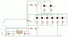
I'm working on a sort of switch, with the following characteristics:
- Iluminated OFF message on the Switch if Off (2 x RED LEDS)
- Iluminated ON message on the Switch if On (2 x WHITE LEDS)
- Back Lighting (4 x BLUE LEDS)
- Ability to switch off Back Lighting (Microprocessor)
- Ability to switch off Ilumination when ON (Microprocessor)
Now, for some reason, my SPICE model started to give me errors (Hate the dreaded software), but the circuit is attached. Can anyone tell me if this will work? Some suggestions perhaps?
I use 2 x 7805's because of the load. I will more than likely replace L1-4 with Ultra Bright LEDs, and the Back Lighting (L5-8) will also almost surely be more than 4 LEDs - and they are Blue")
What I'm not to sure about... Will the 7805's cope with this? If I receive a -5V (from my Microprocessor) at BlackLightsM or BackLightsH, I effectively create a Short on the circuits. Best case scenario I think, I will just end up with a couple of 7805's that gets rather hot. But I don't want to have toasted components either :shock:
Any ways... Can Moses and the other extremely bright people on here perhaps just have a look, and come with some wise words of wisdom for me?
-5V on BlackLightsM Shorts L3 & L4 (Thus, they won't Illuminate when SW1 is ON)
-5V on BackLightsH Shorts L5 - L8, thus no Backlights on the switch
I return either +5V, or -5V back to my Microprocessor to indicate the ON/OFF position of the switch
- 1N4004 is to prevent feedback,
- R1 to cut off some feedback. According to my Splice, I get a weird 1.8V feedback from SW1, regardless of the position. Yes, 10K is overkill, I think I ended up with a value like 120Ohm which is not yet updated on the diagram.
Thanks,
Chris
I'm working on a sort of switch, with the following characteristics:
- Iluminated OFF message on the Switch if Off (2 x RED LEDS)
- Iluminated ON message on the Switch if On (2 x WHITE LEDS)
- Back Lighting (4 x BLUE LEDS)
- Ability to switch off Back Lighting (Microprocessor)
- Ability to switch off Ilumination when ON (Microprocessor)
Now, for some reason, my SPICE model started to give me errors (Hate the dreaded software), but the circuit is attached. Can anyone tell me if this will work? Some suggestions perhaps?
I use 2 x 7805's because of the load. I will more than likely replace L1-4 with Ultra Bright LEDs, and the Back Lighting (L5-8) will also almost surely be more than 4 LEDs - and they are Blue
What I'm not to sure about... Will the 7805's cope with this? If I receive a -5V (from my Microprocessor) at BlackLightsM or BackLightsH, I effectively create a Short on the circuits. Best case scenario I think, I will just end up with a couple of 7805's that gets rather hot. But I don't want to have toasted components either :shock:
Any ways... Can Moses and the other extremely bright people on here perhaps just have a look, and come with some wise words of wisdom for me?
-5V on BlackLightsM Shorts L3 & L4 (Thus, they won't Illuminate when SW1 is ON)
-5V on BackLightsH Shorts L5 - L8, thus no Backlights on the switch
I return either +5V, or -5V back to my Microprocessor to indicate the ON/OFF position of the switch
- 1N4004 is to prevent feedback,
- R1 to cut off some feedback. According to my Splice, I get a weird 1.8V feedback from SW1, regardless of the position. Yes, 10K is overkill, I think I ended up with a value like 120Ohm which is not yet updated on the diagram.
Thanks,
Chris