pixelsnpings
New Member
Hey all.
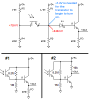
I've been working on an extreamly sencetive IR detector using voltage devision to mark voltage down to the threshold level of a diode aprox - 0.7V.
Heres how its supposed to work...
The Voltage comming from the first voltage devider (R5-R4) is 0.07V
The Voltage comming from the second devider (R1-R2) is 0.63V
The voltage of both deviders therefore is 0.07V + 0.63V = 0.7V.
This should be enough to trigger the diode and turn on the transister.
fliping the VOut line from 0 to 1.
But when I put it to gether it fails to work.
Can someone please look to see if Im missing anything.
I would greatly appreciate any suggestions.