Continue to Site

Welcome to our site!

Electro Tech is an online community (with over 170,000 members) who enjoy talking about and building electronic circuits, projects and gadgets. To participate you need to register. Registration is free. Click here to register now.

  • Welcome to our site! Electro Tech is an online community (with over 170,000 members) who enjoy talking about and building electronic circuits, projects and gadgets. To participate you need to register. Registration is free. Click here to register now.

staged audio amplifier

Status
Not open for further replies.

mstechca

New Member
I think my problem with picking up radio signals is now over. Now, I want to improve my audio section of my circuit.

For each stage, I want to incorporate the following circuit configuration:

The base of the NPN connects to capacitor.
The other end of the capacitor connects to the audio source.
A feedback resistor is connected from base to collector.
A pull-up resistor is connected to collector.
The collector is also connected to the output coupling capacitor.
The emitter is grounded.

For now, I want to ignore the miller effect because I want to go simple.
I normally use a 6V or 9V power supply for all my projects. 6V is used most of the time.

What I want to know is, what are the best values for the resistors to achieve maximum audio volume, and if I were to add another amplifier stage, do I multiply the values of the resistors in the second stage by some number?

I want to feed the entire signal and amplify it.

as far as I know, the capacitors should be 1uF+.

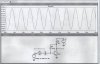
by the way, I did include a half-fast schematic of what I am talking about.
 

Attachments

  • ckt_137.gif
    ckt_137.gif
    3.6 KB · Views: 732
For a second stage, all u have to do is consider the input impedance of the second as the output impedance of the first, for the gain calculation of the first stage. The value of resistors depend upon the gain of that stage, not on any parameter of the previous stage or the next. The overall gain would come out as the product of the individual gains of each stage.

Capacitors in class a amplifiers serve only to provide AC coupling, blocking DC interference with the signal source. Hence the only thing to be kept in mind is the impedance (reactance) that they will offer. Usually, capacitors used in this type of amps range from 0.01 to 1 uF.
 
The transistor has a very low input impedance without an emitter resistor to ground and might load-down your source (what is it?). A second stage like this one will certainly load-down this one.
The transistors will also have a lot of distortion without emitter resistors.
 
I agree with audioguru, for an audio amp, you need a high resistance input, usually 50k.

Your circuit has current feedback which reduces the input resistance.

You need to trsansfer the resistor from the collector to Vcc, connect a resistor from the base to gnd and insert a resistor in series with the emitter.

Len
 
The source is my superregen receiver detector.

For a second stage, all u have to do is consider the input impedance of the second as the output impedance of the first, for the gain calculation of the first stage.
I am totally lost here. How does impedance matching apply with capacitor coupling?

The value of resistors depend upon the gain of that stage, not on any parameter of the previous stage or the next.
Is there an equation to calculate gain based on the resistors?

The overall gain would come out as the product of the individual gains of each stage.
This is about the only equation I know in terms of transistor amplifiers.

Capacitors in class a amplifiers serve only to provide AC coupling, blocking DC interference with the signal source.
Thats why I use them.

Hence the only thing to be kept in mind is the impedance (reactance) that they will offer. Usually, capacitors used in this type of amps range from 0.01 to 1 uF.
So is output impedance equal to RC where R is the resistor from collector to +ve and the capacitor is connected to collector? and is the input inpedance equal to RC where R is the resistor between base and +ve and the capacitor is the capacitor connected to base?

Your circuit has current feedback which reduces the input resistance.
You need to trsansfer the resistor from the collector to Vcc, connect a resistor from the base to gnd and insert a resistor in series with the emitter.
Doesn't that distort the radio signal if I just connect the resistor from base to +ve?, or does the emitter resistor cancel all distortion? and how high should the emitter resistor be?

I want to make an audio amplifier with the best gain and least distortion possible.
 
It looks like your circuit works pretty good. With 10 millivolts input, the output is about 1 volt. You might need a second stage, if the signal is very weak. You will need a volume control between stages or the second stage will overload and distort. The gain is very much dependant on the source impedance, in this case I assumed 10K. If the impedance is lower, the gain will be higher.
 

Attachments

  • amp2.jpg
    amp2.jpg
    64.8 KB · Views: 643
I suggest you look at www.discovercircuits.com

This site should have a variety of audio amps.

As I said before, your circuit will have a low input resistance. But you need a relatively high one.

The voltage gain of the amp that I described is approximately equal to the collector resistor divided by the emitter resistor.

RC is a time constant, not an impedance. The 3 dB breakpoint for an capacitor coupled amp is f = 1/(2piRC) where R is the input resistance of the next stage and this assumes that it is much greater than the output resistance of the previous stage. f is the frequency where the gain is 3 dB (known as the 3 dB breakpoint) lower than the gain at mid range.

You are attempting to understand a complex situation with very limited knowledge. So I suggest you look for a ready made circuit.

Len
 
mstechca said:
The source is my superregen receiver detector.
You must know its output impedance (I can't remember it) in order to design an amplifier with a high enough input impedance so that the receiver's output isn't loaded-down.

I am totally lost here. How does impedance matching apply with capacitor coupling?
A capacitor passes frequencies and impedances. If you connect a circuit (amplifier) with a 1k input impedance to a circuit with a 10k output impedance you get a 1/11 reduction due to "loading-down" by the action of the resulting voltage divider.

Is there an equation to calculate gain based on the resistors?
If a common emitter amplifier stage has a low impedance source and a high impedance load, its gain is simply the value of its collector resistor divided by the value of its unbypassed emitter resistor. The emitter resistor provides negative feedback and allows the transistor's base to be biased easily and securely with a simple voltage divider. The unbypassed emitter resistor vastly increases the transistor's input impedance.

This is about the only equation I know in terms of transistor amplifiers.
You can't just simply multiply the individual gains of transistor stages without investigating the effects of inputs and outputs being "loaded-down".

So is output impedance equal to RC where R is the resistor from collector to +ve and the capacitor is connected to collector? and is the input inpedance equal to RC where R is the resistor between base and +ve and the capacitor is the capacitor connected to base?
You shouldn't simply pick a coupling capacitor's value blindfolded. You might end up with no low frequencies or too much rumble.
The value of a coupling capacitor is determined by the frequency you want to be 3dB down (0.707 of the signal's AC voltage) and is calculated with its "R" as the sum of the source and load impedances.
The output impedance of a transistor stage without current feedback is roughly equal to the value of its collector resistor because a transistor's collector is a fairly high impedance current sink/source.
The input impedance of a transistor stage includes the biasing resistors in parallel and also in parallel with the input impedance of the transistor itself.

Doesn't that distort the radio signal if I just connect the resistor from base to +ve?, or does the emitter resistor cancel all distortion? and how high should the emitter resistor be?
You must bias the base of a transistor so that the output can swing equally positive and negative from its idling voltage. The easiest way is by using an emitter resistor to raise the emitter voltage (and therefore also raise the base voltage) to a known amount, determined by how much the supply voltage and temperature changes, usually 10% of the supply voltage. If unbypassed by a capacitor, the emitter resistor vastly reduces the stage's gain but the distortion (ordinary distortion, not clipping distortion) is reduced by a similar amount. Since the DC voltage required at the transistor's emitter and base are known, the base voltage is established with a simple voltage divider of the supply voltage.

I want to make an audio amplifier with the best gain and least distortion possible.
Doesn't everyone?
Then use many transistor stages with high input impedances and low output impedances, use current sinks and sources instead of collector resistors, use differential stages to cancel even harmonic distortion and use lots of negative feedback. Like an opamp or IC power amplifier.

1) Try it with a 6V supply.
2) Choose a 3.9k resistor for the collector resistor.
3) At 10% of the supply, the emitter's idling voltage will be 0.6V. The collector will swing from 6V to about 1.2V.
4) Therefore the collector's idling voltage will be half the swing which is 3.6V.
5) Therefore the collector and emitter current is 615uA (Ohm's Law).
6) Therefore the emitter resistor is 1k (Ohm's Law again).
7) The base voltage will be about 0.65V higher than the emitter voltage (from the transistor's datasheet) so the base voltage will be about 1.25V.
8) Most transistors have an hFE of about 200 so the base current is about 3uA.
9) Choose a base to ground current of 5 times the base current which is 15uA. Therefore the resistor is about 82k.
10) The 1.25V base to 6V supply resistor will have 18uA, therefore is 264k, use 270k.
 

Attachments

  • transistor_amplifier_stage.gif
    transistor_amplifier_stage.gif
    14.7 KB · Views: 763
Hi Russ,
I figure that your transistor will have about 2.5V at its collector.
The collector voltage and the gain will change a lot with the wide range of hFE values for the transistor. :roll:
With the huge input cap, I figure its lower response is at most 15Hz. :roll:
Can you measure its distortion when it is near clipping? I figure about 12% which is pretty lousy. :cry: :lol:
 
How did you arrive at that figure for input impedance?
 
Hi David,
The input impedance of the transistor is its typical hFE times the 1k emitter resistor (actually it is slightly higher due to the transistor's re), in parallel with the parallel combination of 270k and 82k. :)
 
Here is what the a BJT amplifier looks like when modelled with discrete components, not that the DC biasing supply has been grounded (AC signal is superimposed), the biasing current has been modelled in terms of r(pi). All the other resistances come in parallel, at either the input or the output side. U can now figure the impedance out. The capacitors, if the reactance is very small(1/2(pi)fc <<1) can be ignored.
 

Attachments

  • bjt.jpg
    bjt.jpg
    6.3 KB · Views: 661
audioguru, can you tell me in terms of simplified equations how you reached every value in your transistor design? I'm still lost.
 
Mstechca,
I simply used Ohm's Law. Didn't I explain it clearly?
What don't you understand?

For example #3, the collector's voltage swing:
1) When the transistor isn't conducting, the collector voltage will be 6V.
2) When the transistor is conducting hard, it will have a very low voltage across it and the idling emitter voltage will double to 1.2V.
3) You want the idle voltage of the collector to be half-way between 6V and 1.2V which is 3.6V. Then the collector can swing 2.4V up to 6V and an equal 2.4V down to 1.2V.
Setting the collector's idling voltage is a very important part of designing a transistor amplifier stage.

With the collector's voltage idling at 3.6V, the 3.9k collector resistor has 2.4V across it. Therefore Ohm's Law says that its current (and the series current in the transistor and in the emitter resistor) is 615uA.
Understand? :?: :)
 
For example #3, the collector's voltage swing:
1) When the transistor isn't conducting, the collector voltage will be 6V.
so basically, I have to assume the transistor is not present when it is not conducting, and the resistor is ignored at this time?

2) When the transistor is conducting hard, it will have a very low voltage across it and the idling emitter voltage will double to 1.2V.
This is where I am lost. How did you calculate the resistance and the inductance for the emitter?

3) You want the idle voltage of the collector to be half-way between 6V and 1.2V which is 3.6V. Then the collector can swing 2.4V up to 6V and an equal 2.4V down to 1.2V.
Does idle voltage mean when the transistor is always on, or always off? To me, Idle means stalled in one state.

Setting the collector's idling voltage is a very important part of designing a transistor amplifier stage.
So I always need to make a center collector voltage? If I can't be perfect with the voltage, how much percent can I be off without noticing a huge amount of quality loss?


With the collector's voltage idling at 3.6V, the 3.9k collector resistor has 2.4V across it.
This part is here is confusing me. Where do you get 4V from? and the 3.9K collector resistor has 2 what?
 
mstechca said:
For example #3, the collector's voltage swing:
so basically, I have to assume the transistor is not present when it is not conducting, and the resistor is ignored at this time?
The 3.9k collector resistor pulls the output to 6V when the transistor is not conducting.

This is where I am lost. How did you calculate the resistance and the inductance for the emitter?
You want the idling emitter to be about 10% (0.6V) so that you can set the base voltage accurately. You want the collector voltage to idle at near half the supply so that it has the max symmetrical swing.
Therefore you know the collector voltage and the voltage across the 3.9k collector resistor. Ohm's Law tells you the current.
Didn't you know that the emitter current in a high gain transistor is about the same as the collector current? You know the emitter voltage that you want and now you know its current. Again, Ohm's Law tells you the value of the emitter resistor.

Does idle voltage mean when the transistor is always on, or always off?
Idling is at rest, without input. It is ready to swing positive or negative from this resting voltage or current. If it rested fully on or off, it would be able to swing in only one direction with enormous distortion since it wouldn't be able to swing in both directions like the signal.

So I always need to make a center collector voltage? If I can't be perfect with the voltage, how much percent can I be off without noticing a huge amount of quality loss?
The accuracy of the resting voltage determines the max output signal level before clipping. 20% is close enough.

"With the collector's voltage idling at 3.6V, the 3.9k collector resistor has 2.4V across it."

This part is here is confusing me. Where do you get 4V from? and the 3.9K collector resistor has 2 what?
2.4V is 1/10th of a volt less than two and a half volts. 6.0V - 3.6V = 2.4V.
 
You want the idling emitter to be about 10% (0.6V) so that you can set the base voltage accurately. You want the collector voltage to idle at near half the supply so that it has the max symmetrical swing.
Therefore you know the collector voltage and the voltage across the 3.9k collector resistor. ohm's Law tells you the current.
Didn't you know that the emitter current in a high gain transistor is about the same as the collector current? You know the emitter voltage that you want and now you know its current. Again, ohm's Law tells you the value of the emitter resistor.
So you are saying I should pick a 0.6V for the emitter. Are you selecting the current as well? because ohms law requires two known values of current, voltage and resistance to get the other value.

Did you select the 3.9k resistor, or did you select the current?

2.4V is 1/10th of a volt less than two and a half volts. 6.0V - 3.6V = 2.4V.

Ok. From what I understand, you are saying take the emitter voltage away from Vcc voltage, and subtract the result from Vcc to get Vc?
Why is the emitter voltage subtracted?
 
mstechca said:
So you are saying I should pick a 0.6V for the emitter. Are you selecting the current as well? because ohms law requires two known values of current, voltage and resistance to get the other value.
I selected only the emitter voltage. The emitter current is known to be about the same as the collector current.

Did you select the 3.9k resistor, or did you select the current?
I selected 3.9k for a fairly low output impedance and a reasonable amount of current. You could use 10k or more, recalculate everything else and end up with extremely low current where some transistors don't work very well.

Ok. From what I understand, you are saying take the emitter voltage away from Vcc voltage, and subtract the result from Vcc to get Vc?
Why is the emitter voltage subtracted?
For calculating the idling voltage at the collector, you want it to be near half the supply voltage for symmetrical and largest output swing. But the emitter voltage increases the collector's lowest voltage by about 1.2V when the current is doubled when the transistor is conducting fully. Therefore the collector swings between 1.2V and 6V. Half-way on the total swing is 3.6V.
 
Status
Not open for further replies.

Latest threads

New Articles From Microcontroller Tips

Back
Top