Electro Tech is an online community (with over 170,000 members) who enjoy talking about and building electronic circuits, projects and gadgets. To participate you need to register. Registration is free. Click here to register now.
Welcome to our site! Electro Tech is an online community (with over 170,000 members) who enjoy talking about and building electronic circuits, projects and gadgets. To participate you need to register. Registration is free. Click here to register now.
Thank you for your time and effort in coming up with this design. I have ordered the parts and will connect everything up. Thanks again! I really appreciate it!!
Thank you for your time and effort in coming up with this design. I have ordered the parts and will connect everything up. Thanks again! I really appreciate it!!
Thank you for your time and effort in coming up with this design. I have ordered the parts and will connect everything up. Thanks again! I really appreciate it!!
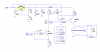
I have used the circuit presented by Roff and it works except for one little problem. When I adjust the pot to set the output to 4.00 mA, I sometimes am unable to set to to 4.00. On the board I am making now, it only goes to 4.02. Would it work to lower the two 10K resistors and use a bigger adjustment pot?? I looked at the AD694 and it looks like it would do the deed but I already have 15-20 boards in use and want to stay with the same design. Thanks!
I have used the circuit presented by Roff and it works except for one little problem. When I adjust the pot to set the output to 4.00 mA, I sometimes am unable to set to to 4.00. On the board I am making now, it only goes to 4.02. Would it work to lower the two 10K resistors and use a bigger adjustment pot?? I looked at the AD694 and it looks like it would do the deed but I already have 15-20 boards in use and want to stay with the same design. Thanks!
Sorry about that.
If you have good access to 1% resistors, change R4 to 9.53k, and change the pot to 1k. This should give you about ±200uA adjustment range at the low end.
EDIT: I forgot that the complete transfer function is
Iout=Vin*(R4+Rpot)/(R3*R1).
Solving for Rpot,
Rpot=(Iout*R3*R1/Vin) - R4
Rpot=200Ω nominal, which is ≈half of R7.
As you said below, ignore my previous suggestion and use 1% resistors.
Ron's circuit needs a dual opamp but a LM324 quad opamp was used. Why not use an LM358 dual opamp that has opamps that are identical to the ones in an LM324?
There is certainly nothing to apologize for. I didn't have 1% resistors readily available and used 5% resistors. From your response, I can see that this is the cause for my predicament. If I had followed your design, it would have worked as I wanted. I will try your suggestion and use the 1% resistors. Thanks for your help!!
There is certainly nothing to apologize for. I didn't have 1% resistors readily available and used 5% resistors. From your response, I can see that this is the cause for my predicament. If I had followed your design, it would have worked as I wanted. I will try your suggestion and use the 1% resistors. Thanks for your help!!
See the edit to my previous post. And Audioguru is right, as usual. I used the LM324 spice model. I should have changed the posted schematic to use an LM358. Too late now, I suppose.
I have already updated the documentation for the 1% resistors. I am using several other 10K resistors on the board and for simplicity (and probably laziness) I added these resistors as 5% originally. The circuit works great for my needs. Thanks for the offer and for providing the initial design. I really appreciate it!!
You can use IC741 by using a single power supply . All you need to do is to make a potential divider circuit taking both resistor value high in order to limit the current entering the IC and connect the junction of 2 resistors to ground . The other terminal of resistors are connected to positive and negative terminals of power supply respectively.
This site uses cookies to help personalise content, tailor your experience and to keep you logged in if you register.
By continuing to use this site, you are consenting to our use of cookies.