Continue to Site

Welcome to our site!

Electro Tech is an online community (with over 170,000 members) who enjoy talking about and building electronic circuits, projects and gadgets. To participate you need to register. Registration is free. Click here to register now.

  • Welcome to our site! Electro Tech is an online community (with over 170,000 members) who enjoy talking about and building electronic circuits, projects and gadgets. To participate you need to register. Registration is free. Click here to register now.

Shorted Canon Camera LP E8 battery .... Help

Status
Not open for further replies.

David Banner

New Member
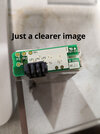
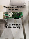
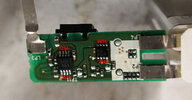
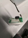
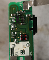
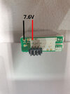
I shorted the + - external connections on the battery for less than half a second. Now the battery is not charging, it is not being recognised in the charger. The camera doesn't see it either. I've opened the battery pack and there are no obvious signs of damage. I am getting reading of DC 7.6v on parts of the pcb (which is correct), but the external terminals are reading 0.151v. I've attached images that I've put some info on. I can do basic multimeter reading where I connect a to b and provide info on the readout.
 

Attachments

  • 1.jpg
    1.jpg
    60.1 KB · Views: 655
  • 2.jpg
    2.jpg
    71.3 KB · Views: 524
  • 3.jpg
    3.jpg
    188.1 KB · Views: 463
  • 4.jpg
    4.jpg
    236.3 KB · Views: 406
I have the same battery for a Canon EOS600D. If there's an easy way to open it I can tell you what voltage should be on tp2, I suspect 3.6 - center tap of battery.

Mike.
 
It likely has both a power FET to disable the output when the battery is low, and a fuse.
Either could have blown because of the short circuit.

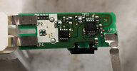
Can you get a better photo of the components on the protection board, so the part numbers are readable?
 
It likely has both a power FET to disable the output when the battery is low, and a fuse.
Either could have blown because of the short circuit.

Can you get a better photo of the components on the protection board, so the part numbers are readable?
Here's a higher resolution version of the image, sorry I had lowered the resolution before uploading them for the first post. I can take another photo, but I wasn't sure what you wanted. I hope you meant this.
 

Attachments

  • 4.1.jpg
    4.1.jpg
    1.7 MB · Views: 423
OK, there are four (or three?) components in a line, that appear to be resistors, at the top left just above "LP2" text.

They may be current sensing resistors, which could be damaged by an overload. Can you measure their resistance?
They look to all be in parallel.
 
Looking again, I realise you are getting voltage at the test points at the other end of the PCB, so the resistors above may be OK.

Look at the smaller 8 pin device; see which pins it has voltage on?
I suspect that is a dual MOSFET, something like this:

And the other IC is likely one of these, from the number on it:

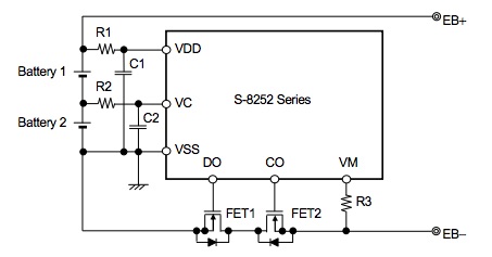
The diagram below is a generic and slightly simplified two cell camera battery diagram, but should give an idea of how things may be connected.

There is a more detailed diagram for the LV5122 on page 11 of its datasheet; very similar, with a bit more info. From that data, if the bank of resistors is current sense, they would probably be connected in series with the FET power circuit; the IC detects an overload by there being excess voltage across the FET switch part.

protection_circuit.jpg
OK, I should explain my situation. I'm fairly stupid so much anything pass the knee bone connects to the head bone type instructions and I am lost. Much enthusiasm but little fuel as a kid left me without the skills for this stuff and life choices took me away from it. I still find myself pulling stuff apart in the hope that I can get it fixed anything really, cars, electrical appliances, anything really, and while I have some luck sometimes I don't. This is how I came to short the battery.

I've attached another image with the pins numbered. Maybe you could let me know what to do regarding which pins to check with what probe and then I could provide a reading from the multimeter.

I totally understand if that doesn't suit, and thanks for everything so far.
 

Attachments

  • 4.2.jpg
    4.2.jpg
    1.7 MB · Views: 326
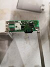
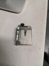
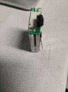
Here are some more general images of the battery setup. I should have sent these to being with, sorry.
 

Attachments

  • IMG_20211023_204928_resized_20211023_085016889.jpg
    IMG_20211023_204928_resized_20211023_085016889.jpg
    183.8 KB · Views: 310
  • IMG_20211024_210257_resized_20211024_090428110.jpg
    IMG_20211024_210257_resized_20211024_090428110.jpg
    639.4 KB · Views: 319
  • IMG_20211024_210304_resized_20211024_090412337.jpg
    IMG_20211024_210304_resized_20211024_090412337.jpg
    559.8 KB · Views: 337
  • IMG_20211024_211339_resized_20211024_091402622.jpg
    IMG_20211024_211339_resized_20211024_091402622.jpg
    508.1 KB · Views: 346
I've attached another image with the pins numbered.
Excellent idea! The numbers as you have them could be confusing though, so I've re-done it using the standard IC pin numbers, so they [hopefully] match the device data sheets.

Canon_Batt_Pins.png

Check between G1 and G4 first, hopefully that will read the same as across the battery terminals (the approx 8V pair)?

If so, can you then measure the voltage from the battery positive contact to every marked pin, eg. labelled G1-G8 and R1-R8 for green and red ICs, that should allow a fair chance at a diagnosis.
 
Excellent idea! The numbers as you have them could be confusing though, so I've re-done it using the standard IC pin numbers, so they [hopefully] match the device data sheets.

View attachment 134219

Check between G1 and G4 first, hopefully that will read the same as across the battery terminals (the approx 8V pair)?

If so, can you then measure the voltage from the battery positive contact to every marked pin, eg. labelled G1-G8 and R1-R8 for green and red ICs, that should allow a fair chance at a diagnosis.
I was working all day today and just got your message I am going to check them now. Thank you.
 
I've triple checked these readings to make sure I wasn't getting any incorrect readings. I've included an image of the battery as tested where the negative strap had been disconnected, But I expect this isn't important. I'd have to make a makeshift connection to get to the back of the board if you want me to text the IC's with the negative band connected. No problem, just let me know.
20211025_212301.jpg

Green
G1. .001
G2. .002
G3. 5.218
G4. 7.61
G5 .001
G6 Varies between 3.4 an 2.9
G7 6.94
G8 7.61

Red

R1 - 5.298
R2 - .004
R3 - 7.61
R4 - 7.61
R5 - 5.312
R6 - 5.316
R7 - 5.320
R8 - 5.320
 
OK; from those readings, it appears the battery controller is in "ready to charge" state., with over-discharge still latched on.
That should be reset by connecting a charger.

The pin G6 voltage reading shows the cells are rather low and that may be holding the output off.


Can you check for continuity between battery positive and one of the external terminals & likewise pin R1 on the FET to another external terminal?

I'm wondering if there is a fuse or blown connection somewhere and one of the external terminals is now disconnected from the rest of the board??
I can unfold the external terminal part and expose the board connections. Lp1 to battery positive is continuous. And Lp5 to Negative terminal is continuous.

When you say another external terminal, please bear with me as I am not that good. Do you mean any of the Lp terminals?

I've included an image of the terminal part folder away from the board. It is still fully connected.

Can you please also confirm if I should be

1. inserting the images into the message
2. Inserting a thumbnail, or
3. leaving them without any insertion as you'll see them as an attachment

From my side I cannot see what you get and with being new to the forum it just dawned on me that if I can insert an image does that mean a non-inserted image doesn't get sent.

Thanks
20211025_222838.jpg
 
I shorted the + - external connections on the battery for less than half a second. Now the battery is not charging, it is not being recognised in the charger. The camera doesn't see it either. I've opened the battery pack and there are no obvious signs of damage. I am getting reading of DC 7.6v on parts of the pcb (which is correct), but the external terminals are reading 0.151v. I've attached images that I've put some info on. I can do basic multimeter reading where I connect a to b and provide info on the readout.
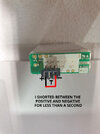
IF you "short" across a load it might be ok (obvious by description u didn't) but by your description i expect you popped your load

buy a new battery
 
I can unfold the external terminal part and expose the board connections. Lp1 to battery positive is continuous. And Lp5 to Negative terminal is continuous.
Strange.. It appear it's just low voltage, and may need to be in the charger for an hour or two to recover?

Re. images, if it's a small one I insert it as is, or for large images / several for info, I insert them then delete (backspace), click the image in the footer and insert as thumbnail.

That allows it to be expanded by anyone reading the thread if they wish, without taking masses of space.

If you go back to the thread after posting, I believe you should see it exactly as other users do, except having the edit option.
OK. I will put it in the charger. But it is not registering in the charger at all. when I say registering, the charger's red light does not come on when the battery is inserted, whereas the red light was coming on before I shorted it.
 
Some chargers only allow a very low current if the battery is below a certain voltage threshold, as lithium cells are wrecked by a deep discharge and can overheat if force-charged from that state.

If the cells are still OK, as those appear to be, the low charge should bring the voltage up enough for normal charging to begin, after some time.

If not, then the power FET (IC with the red numbers) may have been damaged after all..

Can you still measure the cell voltage while it is n charge, to see if is increasing at all?
I might be able to measure it while it's in charge but would that be accurate? I've made a 7.5v battery from regular 1.5 cell batteries to kick off the charging and I'll see does that work and post back. In the interim I've managed to break (by mistake) the terminal connector (black) from the board, so I will have to re connect it before I do anything. Damn damn damn. When I've reconnected the terminal part and see if I can get charge from that 7.5v pack into the canon battery I will come back to you, but it will be a couple of days.
 
Some chargers only allow a very low current if the battery is below a certain voltage threshold, as lithium cells are wrecked by a deep discharge and can overheat if force-charged from that state.

If the cells are still OK, as those appear to be, the low charge should bring the voltage up enough for normal charging to begin, after some time.

If not, then the power FET (IC with the red numbers) may have been damaged after all..

Can you still measure the cell voltage while it is n charge, to see if is increasing at all?
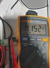
OK, I soldered the terminal back on, took a reading across lP1 lP5 and it was .0152
20211027_213957.jpg
i don't understand
 
Status
Not open for further replies.

Latest threads

New Articles From Microcontroller Tips

Back
Top