Electro Tech is an online community (with over 170,000 members) who enjoy talking about and building electronic circuits, projects and gadgets. To participate you need to register. Registration is free. Click here to register now.
Welcome to our site! Electro Tech is an online community (with over 170,000 members) who enjoy talking about and building electronic circuits, projects and gadgets. To participate you need to register. Registration is free. Click here to register now.
Ronv,
Awsome... I am reading through your post now and will respond accordingly as soon as I have digested all your hard work. Thanks in advance for your time and efforts.
BHinote
Here is my response to your various Questions and/or Comments, in Post #37..
1. 10UFD - Absolutely correct that my schematic was wrong. My original schematic had this set as “10nf”, but this was when I was trying to use “Yenka” for Circuit Design and Simulation. It appears that when I rebuilt this part of the circuit in Multisim my fingers and eyes failed me… .01uf is spot on…
2. S2 - Sorry my oversight. (For Simulation Testing Only.) I cleaned S2 off the Schematic on Post #18, as I was using it during Test Simulation and forgot to remove it during my initial posts. Oops… I hope this did not waste much of your time…
3. R8 – 220 ohms, check.
4. Plating/Silver Solution Question – Actually the whole process/idea is designed to create a “Colloid of Silver Partials”. (Definition: Colloid – “A system in which finely divided particles, which are approximately 10 to 10,000 angstroms in size, are dispersed within a continuous medium in a manner that prevents them from being filtered easily or settled rapidly.”) In other words, super fine partials of silver, positively charged and suspended in Distilled Water. (Colloidal Silver.) Because they are only positive charged they supposedly repel each other lake a bunch of magnets that only have a positive end. (i.e. They become Suspended in the water at a level you can not see with your naked eye, unless you shine a laser through the water…)
5. Resistance of Water – Based on what I have read as well as observed with my own experiments, The only “Plating” that could occur is in the form of a dark sludge that could form on the Negative Electrode and does not appear to be plating at all. However according to my research, this could be minimized or possibly avoided with polarity switching circuitry. From everything I have read and observed, resistance starts out very low and escalates from there. Without a Constant Current Managing Design, the current exponentially increases as the resistance increases. (This has been termed as “Current Runaway” and is not a desirable result within the research I have adopted to be true.)
I will look over the schematic you have provided and the comments that follow and get back to you as soon as I can.
Simple words can not convey my feelings, but I am very grateful for all of your time and efforts.
Motor was mistakenly left in my initial schematic and was corrected in my updated post.
I agree with your comments regarding the use of a magnetic stirrer, as I have already built and completed this part of the design. (i.e. PWM Circuit w/Potentiometer, Revamped Case Fan mounted under a Coffee Maker's Hot Plate, Scavenged Rare Earth Magnet from a Hard Drive and a Retail Magnetic Stirring Bar.) It is working "Perfictly"...
BHinote
The whole point is to get the silver into the solution and to have as pure of a silver/water mix as possible.
Just as you would use an AC voltage for water detection, you use AC here. The crud builds up on one electrode and you have to remove it by reversing the polarity. This method is typical for electrochemistry.
I would guess the motor is a stirrer. If it is, I'd use a magnetic stirrer. Best would be a stirrer/hotplate. **broken link removed**
OK. I could not get the LM317 to act right for all the conditions, so here is the Fry's special.
Sorry, it is a bit more complicated but I think it will work for you.
Here are some things I noticed along the way.
The 10Ufd on the Con pin of the 555 should be a .01ufd.
You should have a 10 ufd. from 5 volts to ground at the 555.
I simulated with 4.7 Ufd. for the timing cap on the 555 and get 3 seconds or so with the pot at 50%. That would make your timing 300 seconds at 50%. I'm guessing this is what you want.
I didn't know what S2 Motor was so I tied the input of the NOR blocks to ground to make them active. Is S2 a timer or something?
I would make R8 220 ohms for the LED.
So here are the changes:
Replace the 317 with a current source.
Replace the base resistors with 150K,
Replace the transistors with Fry's available.
With this setup the single pot should get you from 1ma to about 12 or so.
I'm not sure I understand how this works since it would appear that it just plates from one electrode to the other and then back again. Does some of the silver stay in solution?
If so it won't take long for the resistance of the water to go down.
5. Resistance of Water – Based on what I have read as well as observed with my own experiments, The only “Plating” that could occur is in the form of a dark sludge that could form on the Negative Electrode and does not appear to be plating at all. However according to my research, this could be minimized or possibly avoided with polarity switching circuitry. From everything I have read and observed, resistance starts out very low (High) and escalates from there. Without a Constant Current Managing Design, the current exponentially increases as the resistance increases (decreases). (This has been termed as “Current Runaway” and is not a desirable result within the research I have adopted to be true.)
Comments:
I made my changes in bold.
This has the corrolary to the blurb about stopping the process that you mentioned in (1) earlier. Resistivity which is a material property should be able to be used to stop the process. It's routinely used to determine the quality of a DI water system. As I outlined earlier, possibly a little backwards), you can determine the "resistance" of the water and back out resistivity knowing the geometry. If all else is the same (geometry, current, electrode size), then the voltage measured at the electrodes with a constant current can be used to terminate the reaction. This is a constant current reaction.
The bigger the electrode the more current needed and the more expensive the silver. There will be a big difference with a 1 square foot electrode and a 1 square inch electrode.
As the spacing is increased, a higher voltage is needed.
Everything else I agree with.
Stirring will keep the bubbles from forming at the electrodes. Bubbles reduce the effective area of the electrodes and thus detrimental.
Of course you are right about the start out and ending resistance… I could try to blame my incorrect response on a long day and a 2:49 am reply, but honestly I just wrote it wrong… ;-) You know the old “More is More” and “Less is Less” thing. (Wrong… Less is More and More is Less when it pertains to Resistance.) Thank you for the correction.
Thanks for the data sheet.
General Question:
Because I do not have the practical knowledge or understanding in electronics, I have a question about the use of Q6(BC547C) vs. Q5(BC547B) on the Left and Right side of the Bridge. Why are different ranges of current gain used? (Simplton Logic, like my own, would thing of each side being like a light switch in my house. With the same type of switch and the same type of Light, if I flip the left one on the left light comes on. If I flip the right one on, “presto” the Right Light comes on…) I am obviously naive to the rules and requirements here…
BHinote
Thank you, but they are about 4 hours from where I live...
Since Radio Shack will most likely not have what is needed and my next trip to Sacramento, ca will not be until next weekend. I will just order what is needed as soon as the last "Proverbial Nail" is Virtually pounded home...
"I can see the light, even if I personally am not sure how the darn thing was turned on..." LOL
Got it... I should have read this before asking my BC547C & B question, with the whole Light Switch analogy... They are the same switches now…
Thanks again.
BHinote
Current gain (Hfe) is one of those parameters that just can't be controlled on the money. In fact, we go through a LOT, of headaches just to make an amplifier work OK for a range of Hfe.
Thanks again for building and testing a schematic on your end making it available to me. I believe that I have recreated your work to the best of my ability and the Multisim's available parts...
Anyway I have spent 4 or 5 hours trying to get Multisim to run the simulation without throwing an error, but I can not seem to get it to run for more that 4 or 5 seconds without popping an error about "Timestep too small" It is my understanding that this is more of a catch-all message when the software is having a problem trying to nail down some type of an algorithm for a component. (i.e. It tries one algorithm that isn't quite right and then tries another and so on, etc... Eventually it times out...)
This is not to say that your design is not spot on, just that I have either made a mistake or the software is having a problem with a circuit that works in the real world...
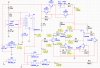
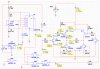
Anyway I have attached to images of the few results that I was able to retrieve. The first is my representation of your design. The second is a test I did eliminating the Current Limiting circuitry and substituting a 10ma current source.
I am not sure I am interpreting the results correctly, but I am not sure why the source starts out @ 10ma yet appears to end with 5.43ma near R3...
Sorry to trouble you after you have already done the work, but I thought you may be able to see the error of my ways...
OK. I could not get the LM317 to act right for all the conditions, so here is the Fry's special.
Sorry, it is a bit more complicated but I think it will work for you.
Here are some things I noticed along the way.
The 10Ufd on the Con pin of the 555 should be a .01ufd.
You should have a 10 ufd. from 5 volts to ground at the 555.
I simulated with 4.7 Ufd. for the timing cap on the 555 and get 3 seconds or so with the pot at 50%. That would make your timing 300 seconds at 50%. I'm guessing this is what you want.
I didn't know what S2 Motor was so I tied the input of the NOR blocks to ground to make them active. Is S2 a timer or something?
I would make R8 220 ohms for the LED.
So here are the changes:
Replace the 317 with a current source.
Replace the base resistors with 150K,
Replace the transistors with Fry's available.
With this setup the single pot should get you from 1ma to about 12 or so.
I'm not sure I understand how this works since it would appear that it just plates from one electrode to the other and then back again. Does some of the silver stay in solution?
If so it won't take long for the resistance of the water to go down.
BH,
The 150 ohm resistors should be 150K.
LTSpice had trouble finding the operating point when I attached the IC's. Don't know what that was about either. I think it may work better with the 150K's.
True, but again my biggest issues have been with cross referencing parts... I walk in with Names, Numbers and/or codes that obviously do not match Radio Shacks numbers. Radio Shack on line is 0% help in cross referencing and almost never finds its own parts.
I do not expect or ask the people working there to try to figure out electronic circuitry, but I ask them if they have any resources to cross reference the parts and the answer is "NO". I ask them if they source their components from a particular distributor so I can try to look it up before coming in and I get the "puzzled look followed by the I am not sure reply..."
I am sure someone that actually knows that a XX4132bd, a LT123 and a 425-1234ap are all the same component will handle radio shack just fine, but when I go in looking for a XX123 Transistor and find package with no statistic printed on the package and not knowing which of the 15 Transistor actually does what I need I end up with lots of cool components sitting in the bag on my desk... LOL However if you were to ask me to pickup some resistors and "maybe" a capacitor or two, I am all over that... ;-) I hope you are laughing right now, as this was the intent of my reply...
To be honest if I had started this project actually trying to teach my self electronics, I may have been more self sufficient by now. I knew electronics, like everything else, required education, but I was hoping to find similar projects "logically" put them together and then use my mechanical ability to produce the result. "Gong....." Not this time....
I greatly appreciate all the time and effort both of you have provide me and hope I have not burn either of you out just yet...
Regards,
BHinote
BH,
The 150 ohm resistors should be 150K.
LTSpice had trouble finding the operating point when I attached the IC's. Don't know what that was about either. I think it may work better with the 150K's.
Prefixes usually refer to the manufacturer. Thus an LM555, uA555,= and a NE555 are the same part. Then someone comes along like www.nteinc.com who makes replacement semiconductors with their own numbering system and calls it an NTE9555. CD4053 and an MC4053 are the same too and sometimes it's just referred to as a 4053 just like the 555 is. Suffixes could mean accuracy or temperature range etc. There may be date codes on an IC and country of origin codes.
Now there are "markings" and I havn't figured them out at all. There isn't enough room on a component to put all the numbers.
A 100 ohm resistor could be 100 ohm, 101. On a schematic it could be 100, 100R, 100., 100 Ω
Yea. it's a mess. I've been doing this since I was maybe 10 years old when there were tubes. Surface mount is driving me nuts.
LOL... It is good to know that even a "Veteran" (i.e. Years of Experience...), like yourself, might have to pause from time to time and say "Now what the heck have they gone and done..."
Thanks for the simplified understanding of Name/Numbering... I thought a 40## might be the same if it were a LM40## or a NTE40##, but at some point over the past couple weeks I tried to use this conceptual idea with Multisim and found that the core number I was looking for was something entirely different when it was placed on the schematic... Go figure...
Now that I have recreated Ronv's Circuit, I am looking back at a couple of your suggestions to see what they might do as well.
Prefixes usually refer to the manufacturer. Thus an LM555, uA555,= and a NE555 are the same part. Then someone comes along like www.nteinc.com who makes replacement semiconductors with their own numbering system and calls it an NTE9555. CD4053 and an MC4053 are the same too and sometimes it's just referred to as a 4053 just like the 555 is. Suffixes could mean accuracy or temperature range etc. There may be date codes on an IC and country of origin codes.
Now there are "markings" and I havn't figured them out at all. There isn't enough room on a component to put all the numbers.
A 100 ohm resistor could be 100 ohm, 101. On a schematic it could be 100, 100R, 100., 100 Ω
Yea. it's a mess. I've been doing this since I was maybe 10 years old when there were tubes. Surface mount is driving me nuts.
This site uses cookies to help personalise content, tailor your experience and to keep you logged in if you register.
By continuing to use this site, you are consenting to our use of cookies.

")