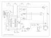
In the attached circuit (I hope it shows up), power is supplied by a gang of 8 AA batteries. The motor is allowed to rotate only about 4 turns, as it pulls a cable by wrapping it around the motor shaft. One end of the cable is clamped to the motor shaft and the other end is attached to a spring loaded catch.
The circuit is designed to allow operation of the motor only when the switches are pressed in the correct sequence. There is a default sequence of 1-2-3-4, but the user can input his own sequence as well.
My first question is about what happens once the motor pulls the cable. What keeps the motor from drawing current once the latch is opened? The motor is only powered in one direction, as a spring pulls the cable back, which in turn turns the motor back to its starting position. So what in the circuit turns off the motor current, and how does it know when to turn it off?
I know that the MOSFET Q4 directly switches the motor's ground path, and that the MOSFET is controlled by U1. But how does U1 know to switch Q4 off?
My next question is about D2. Is that there just in case the batteries are put in backwards? What about D1 and D3? What are they there for?
What do Q1, Q2 & Q3 do?
Can anyone help me to understand this? I drew the schematic from the board, which quit working. Q4 appears to be shorted, and there is charring on the board at the end of C9 that goes to J1. I think that the motor stayed "on", which might have caused the failure of Q4. Does that make sense?
I'd like to repair this board. The maker won't service it -- they only want to sell me an upgraded safe.