Continue to Site

Welcome to our site!

Electro Tech is an online community (with over 170,000 members) who enjoy talking about and building electronic circuits, projects and gadgets. To participate you need to register. Registration is free. Click here to register now.

  • Welcome to our site! Electro Tech is an online community (with over 170,000 members) who enjoy talking about and building electronic circuits, projects and gadgets. To participate you need to register. Registration is free. Click here to register now.

Problem finding Opto Triac S201S01

Status
Not open for further replies.

NewcastleSAR

New Member
Hi Folks..

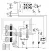
I'm attempting to build the Darkroom timer from the April 2001 edition of Eleckor Electronics but have hit a bit of a snag.

I'm having trouble obtaining IC3 which is an Opto Triac S201S01 (Sharp) (Conrad # 16 81 65)

Anyone know of a substitute for this. I've gone to the Conrad website but the available of it is 'Red'

I intend to use this with a PCB Exposure board that I am making using an old computer scanner. The time unit will hopefully assist in 'timing' the exposure rates.

Many thanks

Declan
 
Hi Folks.

I've just discovered that a replacement is the S201S05. I've managed to find a supplier .. in Ireland.. of all places - not far from me.

The only thing is, I've had to email them to see if they actually have any in stock.

Declan
 
Hi Folks..

It looks like I may have hit a dead end in finding a replacement for the S201S01 Opto-Triac.

Could a kind soul take a look at the attached file and possibly recommend a way around the problem. The problematic chip is IC3.

Regards

Declan
 

Attachments

  • timer.JPG
    timer.JPG
    60.9 KB · Views: 1,737
The way I'd do it, would be to use a relay. Driven from the pic via a suitable transistor and back-emf diode.
Alternatively, download the spec sheet of the S201S01 and try to find a similar valued one (that is available), in the same sized package.
 
What sort of output current do you require?

I would normally use the MOC3041 but if I needed more current I'd add another buffer triac.

How about posting the datasheet for the S201S01?

I've done a quick Google and I couldn't get it from a site that doesn't require a subscription,
 
Hi All..

This is the PDF document of the project. I've had to remove the main graphic on the front page so that I could get the document small enough in size to upload

Regards

Declan
 

Attachments

  • e014032b.pdf
    545.9 KB · Views: 667
S202S02 available

NewcastleSAR said:
Hi Folks.

I've just discovered that a replacement is the S201S05. I've managed to find a supplier .. in Ireland.. of all places - not far from me.

The only thing is, I've had to email them to see if they actually have any in stock.

Declan

Hi Declan,
by chance I discovered your trouble for looking after a solid state relay. I have a similar, pin compatible unit named S202S02 available, which is "the big brother" of the s201s01, capable of switching up to 8 Amps @ 250V 50/60Hz

The pinning an mechanical size is equivalent to the pdf you posted for the s201s05, so I think, this should be suitable for your needs. No change of circuit, PCB, etc.

The S202S02 has zero crossing detection built in, but I think this won't be any problem for this application, since you just switch 100% on or off, as I understand.

I have some of these available, if there is interest, send me a personal message with your needs.

Kind regards

Andreas
 
Last edited:
Hi Seafian..

I've posted a PM to you. One thing that slipped by me is that if you look at the PDF for the Project, it marks IC3 as S201S02 in the circuit diagram but in the component list, it is marked as S201S01.

I'm now wondering which one is correct and based on this, which substitute do I use?

If only I could get my hands on the datasheet for the S201S01.

It seems from trawling the internet the that the following are alternatives:

S201S05 for the S201S01 and the S201S06 for the S201S02

Regards

Declan
 
Hi Declan,
you've got PM too.

Looking at the Elektor circuit I've seen that discrepancy too, but to my understanding both versions can be used.

S201S01 is the SSR (solid state relay) without zero cross detection while S201S02 includes zero crossing detection.

The zero cross detection controls the switching or "firing" of the main triac (inside the SSR) shortly after the zero crossing of the mains voltage. This reduces electrical noise (disturbances, EMC etc) of the circuit so you don't need to synchronize the SSR control voltage with the mains frequency.
On the other hand this behaviour prevents the use of the SSR for phase control applications like dimmers, for those you need to use the S01 version.

Coming back to your darkroom application I think there is no need for mains phase control since you just want the lamp being switched fully on or off, no dimming or any other power control is needed. Both the S01 and S02 versions can do the job. The PIC will just leave the control output on for the desired duration set by the switches, and this will be in the range of seconds to minutes, as I understand the use of the timer.

for further info on the SSR see
https://www.electro-tech-online.com/custompdfs/2006/12/s102s01_e.pdf

and/or

https://www.electro-tech-online.com/custompdfs/2006/12/s102s02_e.pdf

Hope I could be of help
Regards
Andreas
 
Hi vahdat,

what kind of power device? For AC, DC, what wattage, isolation between control and power circuit or not? Any known type number?

rgds
seafian
 
Triac Usage

Hi people,
I am a begginer in usage of Triacs. I want to use it for switching an AC load.
I am not aware of using it in a circuit in which the Triac is triggered by an External High signal. Once I tried to connect it across 230 V AC supply and a load. The Triac burst. Please help me.
Regards,
Vijay
 
Status
Not open for further replies.

Latest threads

New Articles From Microcontroller Tips

Back
Top