Continue to Site

Welcome to our site!

Electro Tech is an online community (with over 170,000 members) who enjoy talking about and building electronic circuits, projects and gadgets. To participate you need to register. Registration is free. Click here to register now.

  • Welcome to our site! Electro Tech is an online community (with over 170,000 members) who enjoy talking about and building electronic circuits, projects and gadgets. To participate you need to register. Registration is free. Click here to register now.

PICAXE 08M2 Unipolar Stepper Motor Controller Schematic

Status
Not open for further replies.

tracecom

New Member
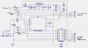
Attached is a schematic for a unipolar stepper motor controller using an 08M2. It has a built in 5V power supply that uses the 12V stepper motor power source as its input. It is designed to control the stepper motor either (a) via programming completely contained within the 08M2, or (b) via simpler programming contained within the 08M2 that is controlled by external circuitry. The external circuity could be another PICAXE that simply sends high signals on the input lines, or switch/relay contact closures that switch the 5V back to the 08M2.

Comments and suggestions are wanted. (I posted this on the PICAXE forum, but didn't get much response.)

Thanks.
 

Attachments

  • PA-08M2 Unipolar Motor Driver.jpg
    PA-08M2 Unipolar Motor Driver.jpg
    158.5 KB · Views: 3,613
Hi Tracecom (and hi James!) it will be limited to full step and half-step mode as the 2803 cannot perform any current control (can just turn windings on and off).
 
Microstepping is generally supported by turning the winding on and off, but at a duty cycle that is something between 0 and 100 percent. PWM output from the PICAXE would support that.
 
Do you realize this can be done with just 2 output pins of the picaxe driving the darlington driver, this is covered very well in picaxe manual 3 under "Interfacing Circuits" and is why you might not have received much of a response on the picaxe forum, it has also been covered many times by many people.

If you want to use half stepping then the use of the 4 output pins would be needed, and i would recommend you try half stepping as the motor will run much smoother with more torque.

It is really a bit useless posting the schematic if you are not prepared to post the code to suit.

Pete.
 
Do you realize this can be done with just 2 output pins of the picaxe driving the darlington driver, this is covered very well in picaxe manual 3 under "Interfacing Circuits" and is why you might not have received much of a response on the picaxe forum, it has also been covered many times by many people.

If you want to use half stepping then the use of the 4 output pins would be needed, and i would recommend you try half stepping as the motor will run much smoother with more torque.

Yes, I have tried the toggle approach, but the resulting torque was inadequate. In fact, that is the reason I doubled up on the 2803 circuits - to be able to run larger motors.

It is really a bit useless posting the schematic if you are not prepared to post the code to suit.

Pete.

My goal was to get some additional eyes on the hardware schematic, and look for errors as I plan to go straight to PCB with the design.

I have not written the code for this particular application. However, the code just to turn the motor follows. Note that I wrote it for an 08M instead of an 08M2, but it should still run if the pinouts as called for in the code agree with the schematic (which I haven't checked.)
Code:
'Drive unipolar stepper motor with increased torque. PICAXE-08M

symbol delay = 3		'pause duration (must be at least 1 ms.)
let dirs = %10110	'sets pins 4, 2, and 1 as outputs
				'pin 3 is always an input; pin 0 is always an output

cw:				'clockwise rotation
	let pins = %10001	'windings 2b and 1a
	pause delay
	let pins = %00011	'windings 2a and 1a
	pause delay
	let pins = %00110	'windings 1b and 2a
	pause delay
	let pins = %10100	'windings 2b and 1b
	pause delay
	goto cw		'endless loop
 
Last edited:
If you are going to PCB have you considered using 4 FETs? It's a similar amount of soldering to a ULN chip, and very little extra cost or PCB size. But will give you a much improved current rating. :)
 
If you are going to PCB have you considered using 4 FETs? It's a similar amount of soldering to a ULN chip, and very little extra cost or PCB size. But will give you a much improved current rating. :)

You mean like this? ;)

Yes, I have actually protoyped this circuit, but its higher component count, PCB real estate, and cost may work against it. But, you're right that I should think it over again.

Oh, and here's the code.

Code:
'North American Phillips A82719 Stepper Motor Driver
'This is a unipolar motor with 7.5 degree steps. It runs well on 12vdc, and draws about 370
'milliamperes.

output b.4, c.3, c.4, c.5
symbol msecs = 50 'Must be at least 3 or motor will not turn; probably should be at least 4 in order
			'to allow motor sufficient time to avoid motor missing pulses.
cw:	for b1 = 1 to 10	'Sets number of complete revolutions clockwise.
		for b0 = 1 to 12	'12 loops = 48 steps = 360 degrees clockwise.
			high b.4: low c.3: low c.4: high c.5
			pause 4
			low b.4: low c.3: low c.4: low c.5 'Removing power from the motor allows cooling.
			pause msecs	
			high b.4: high c.3: low c.4: low c.5
			pause 4
			low b.4: low c.3: low c.4: low c.5 'Removing power from the motor allows cooling.
			pause msecs
			low b.4: high c.3: high c.4: low c.5
			pause 4
			low b.4: low c.3: low c.4: low c.5 'Removing power from the motor allows cooling.
			pause msecs
			low b.4: low c.3: high c.4: high c.5
			pause 4
			low b.4: low c.3: low c.4: low c.5 'Removing power from the motor allows cooling.
			pause msecs
		next b0
	next b1
low b.4: low c.3: low c.4: low c.5 'Removing power from the motor allows cooling.
pause 2500

ccw:	for b1 = 1 to 10	'Sets number of complete revolutions counter-clockwise.
		for b0 = 1 to 12	'12 loops = 48 steps = 360 degrees counter-clockwise.
			low b.4: low c.3: high c.4: high c.5
			pause 4
			low b.4: low c.3: low c.4: low c.5 'Removing power from the motor allows cooling.
			pause msecs
			low b.4: high c.3: high c.4: low c.5
			pause 4
			low b.4: low c.3: low c.4: low c.5 'Removing power from the motor allows cooling.
			pause msecs
			high b.4: high c.3: low c.4: low c.5
			pause 4
			low b.4: low c.3: low c.4: low c.5 'Removing power from the motor allows cooling.
			pause msecs
			high b.4: low c.3: low c.4: high c.5
			pause 4
			low b.4: low c.3: low c.4: low c.5 'Removing power from the motor allows cooling.
			pause msecs
		next b0
	next b1
low b.4: low c.3: low c.4: low c.5 'Removing power from the motor allows cooling.
pause 2500

goto cw
 

Attachments

  • 20X2 IRLZ44N Driver Schematic.jpg
    20X2 IRLZ44N Driver Schematic.jpg
    236.6 KB · Views: 1,992
Last edited:
Yep that looks fine. :)

I would suggest a couple of changes to your FET gate resistor values, the 100k could be changed to 1k and the 330 ohm resistors reduced to 33 ohms or just left out as the PIC output pins have a resistance of more than 33 ohms anyway. :)
 
Status
Not open for further replies.

Latest threads

New Articles From Microcontroller Tips

Back
Top