Continue to Site

Welcome to our site!

Electro Tech is an online community (with over 170,000 members) who enjoy talking about and building electronic circuits, projects and gadgets. To participate you need to register. Registration is free. Click here to register now.

  • Welcome to our site! Electro Tech is an online community (with over 170,000 members) who enjoy talking about and building electronic circuits, projects and gadgets. To participate you need to register. Registration is free. Click here to register now.

Operating Frequency of NPN Amplifiers.

Status
Not open for further replies.
starting objective

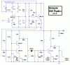
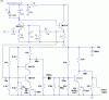
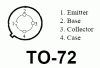
I,ve been trying to build a decent radio for about 2 years. At first, I just read up on whatever I could about simple crystal radios and started building them, but I am not satisfied with that. I want to learn how to use transistors in my circuits to enhance the operation and power of my recievers. I have checked out almost every book from my local library on the subject,and I have learned alot. However, I am still unclear how the little 3-pronged devils work, how to bias them for the desired result, and all the little nuances of placing the different biasing types in a circuit. I have built about 30 different radios from other people's schematics,all crystal sets and AM band. Some worked,some didn't, and a couple worked great. But it's kinda' like copying a book someone else wrote- it looks good, but it don't make me a writer. I want to learn how to build radios for any frequency range I want to listen to, and that is why I asked the question-"how do you bias a transistor for a given frequency range?" I saw this site and thought I would ask the qustion, and after the responses I've recieved, I feel like an idiot for not coming here 2 years ago.
 
I'm not really familiar with what NTE has to offer. NTE316 has high Ft (current gain-bandwidth product) and low collector-base capacitance. Both these parameters are important in RF amplifiers. There are probably others that are as good or better for what you want to do.

To bias a transistor, remember these facts:

1. Collector current ≈ emitter current.
2. Vbe ≈ 0.7V
3. Base current is Ic/ß (ß is beta or Hfe). Therefore, base current is low, but it can't be ignored. However, depending on the biasing technique, it can be insignificant.
"Biasing for RF" is not black magic. Be aware that collector-base capacitance increases as Vcb decreases. High collector-base capacitance is the enemy of RF amplifiers everywhere. :(
 
NTE316

Thanks Ron. I looked up the store's site and they have plenty of the NTE316/2N5179 transistors on hand,on Monday I can pick up 10 for $1.60. I am assuming I can replace all of the transistors in the earlier circuit,as long as none of them exceed 50mA? I hand-copied the earlier circuit and added the bypass from the top of the tank to ground, the 10k resistor between the tank and +V, and direct coupling to the base of Q2. This circuit really isn't difficult at all, I wouldn't mind building it to see how it works,especially since I already have 1/2 of it made.
 
Re: NTE316

Reitan said:
<snip>I am assuming I can replace all of the transistors in the earlier circuit,as long as none of them exceed 50mA? <snip>
That should work. You might want to stick to the 2N2222 for the audio amp stage.
Just a warning (now he tells me): High Ft transistors are prone to oscillate if they have inductance (long wires) in the base circuit, and/or capacitive loading on the emitter. It probably won't be a problem, but if a transistor does oscillate, it can cause mysterious symptoms. If one does oscillate, you can sometimes cure it with 100 ohms or so in series with the base. You will also need good power supply decoupling and a good ground plane.
 
Re: starting objective

Reitan said:
I want to learn how to build radios for any frequency range I want to listen to, and that is why I asked the question-"how do you bias a transistor for a given frequency range?" I saw this site and thought I would ask the qustion, and after the responses I've recieved, I feel like an idiot for not coming here 2 years ago.

Really you don't bias the transistor for the range, the range is set (mostly) by the tuned circuits in the design.

It's becoming one of my most common suggestions, but you should try and get a copy of either the ARRL or RSGB handbooks, which should help you a LOT!. An old copy would be fine, you don't need to splash out on a new one!.
 
In my "super simple SW crystal radio", I fixed the bootstrap, used RF transistors, reduced the value of some resistors and used an RF cacode pair of transistors. :lol:
 

Attachments

  • simple_sw_radio_491.gif
    simple_sw_radio_491.gif
    15.6 KB · Views: 692
Thank you audio guru! I will copy that schematic and give it a shot. I played with the tank circuit yesterday and I pulled in WWV hawaii as well as another talk station. I heard a couple others also, but they were to faint to identify.It helped tremedously to bypass the positive end of the tank,it almost doubled the clarity!(thanks Ron!) I have built a new antenna, a horizontal 5 meter,painted to blend in with the living room wall(kinda'),my wife loves that. Even though it only runs 1 meter down to my bench, I still used a shielded cable. I am hoping that will help somewhat with my input.I will probably have the radio built by Thursday, again I will post the results. I appreciate everyone's time and help.
 
I like it! - But I like this emitter follower biasing scheme better (fewer parts). The tank has millivolts of RF across it, so Vce on Q1 doesn't need to be high. The 1k resistor in series with the tank also effectively decouples the tuned amp from the broadband amp, reducing the risk of oscillation due to poor power supply decoupling. In fact another RC on the cascode amp power supply side might not hurt.
Audioguru, I removed your title block, just in case you were attached to it. :) You can add it back if you make more changes. :D
 

Attachments

  • simple_sw_radio_493_571.gif
    simple_sw_radio_493_571.gif
    13.5 KB · Views: 671
Thanks again! I probably would have oscillation problems because of the way I'll lay it out. I've taken to cutting my own circuit designs out of thin copper plate, and for this one I will also need to cut out a ground plane for the top side of the board as well. This will be a few hour adventure, as I will likely superglue myself to random objects on my bench several times before it's over. I will probably go with the latest revised circuit for that reason. So basically, any frequency I set the tank for, I will pull it in? I built a nice, 22uH coil today with taps down to 5uH. I have also upgraded my capacitor network for a tunable range of 195pF to 237pF with some ceramic capacitors to give me better station seperation. My coil has 10 taps, so there will be some band overlap. I am guessing I should get from 2.2MHz up to 5MHz.I also am making a slow-motion dial, that should help too. I will use shielded cable to link the tank to the circuit board, using the ground to help eliminate interference, and my capacitor network is also laid out on a small piece of circuit board to cut down on the effect of all the leads sticking out everywhere. Will this new tank set-up work with the revised circuit?
 
I duly noted the change of R1 to 470 ohms,and my parts will be available for pickup in 2 hours.I might be able to build this thing tonight. I'l let everyone know how this thing perfoms,with my crappy layout,at least. But I also ordered 3 times more parts than I needed in case I mess up the first one!
 
2N5179 Problem

I sprung for a circuit board kit and I just got that finished, so I started solderng components on it and I reached into my tray for a 2N5179, located the tab to find the emmitter lead, and damn! There is 4 leads on these! What's more,2 of them are centered on the tab, so which one is the emmitter? And what do I do with the extra lead? I rechecked the part number on it about 50 times, and it's definately a 2N5179. What gives with this one? I've got everything ready to complete this project tonight except this critical piece of info. Anyone out there know the answer to this one?
 
RF transistors often have a fourth wire for a screen, I suggest you google for a datasheet to find the connections!.

The screen simply connects to the 0V rail of your circuit!.
 
Thank you Nigel! I was thinking I might have to solder the extra lead to the ground plane when I read your message. I'll look real quick, but usually those data sheets are all in javascript, and my poor old webtv can't handle it. I appreciate the help- again!
 
I appreciate the link,Nigel. Unfortunately, my webtv won't let me see it. I did build the radio, but I know I have the transistors funny because it don't work. I also noticed something funny about the transformer I used for the power supply. It's 115VAC to 9VDC at 200mA, but on my meter it reads 15VDC. I thought it was just my meter acting strange when reading the transformer,but now I'm not so sure. I should be able to find a different one somewhere,plus I will play wiyh my transistor layout.Hopefully I didn't smoke anything in my circuit. Now that I think about it, the house is a little smoky.....
 
Reitan said:
I also noticed something funny about the transformer I used for the power supply. It's 115VAC to 9VDC at 200mA, but on my meter it reads 15VDC. I thought it was just my meter acting strange when reading the transformer,but now I'm not so sure. I should be able to find a different one somewhere,plus I will play wiyh my transistor layout.Hopefully I didn't smoke anything in my circuit. Now that I think about it, the house is a little smoky.....

It's obviously an un-regulated supply, they are absolutely CRAP! - 15V sounds about normal for a 9V supply!, the 9V is under full load.
 
If you still need the pinout, here it is.
I have to confess I'm not too thrilled about our choice of transistors. That package brings back bad memories from about 1970, when I was breadboarding a high-speed sample-and-hold. I had an RF transistor (I don't remember the part number - probably 2N918) in that package that was oscillating at some ridiculous high frequency. It was a common base stage (!), and in order to shorten the leads, I had gone to the extreme of drilling a hole in the GND plane, soldering the transistor upside down into the hole, soldering a chip cap from the base lead to the GND plane, ... it still oscillated. Somewhere I have a picture of me, hammer high over my head, ready to smash the breadboard to smithereens. I can't remember how I tamed the oscillation, but it was probably with 47 ohms in the base lead or a ferrite bead slipped over it.
Anyhow, I hope you don't have similar problems. If you do, try something a little tamer, like MPSH10, or maybe one of the other guys can suggest something.
I originally suggested 2N5179 only because I had a Spice model of it. It is probably overkill for 4MHz.
 

Attachments

  • 2n5179_pinout.gif
    2n5179_pinout.gif
    3.5 KB · Views: 758
Well, I switched the power supply to 8.5V,double checked everything on the board,the only thing that could be preventing the thing from working is the lead orientation on the 2N5179's. I found a site with a picture of the leads,but it was a 2-dimensional circle with 4 leads and the tab on the case was in the 8 o'clock position. I assumed it was a view from the top, but now I'm not so sure. It showed the emmitter at the 9 o'clock position, and the sheild at the 6 o'clock position. The base was at 12 and the collector was at 3. Anyway, this simple shortwave set is turning out to be everything except simple. It would be a simple matter to just keep testing different configurations, except I would have to adjust all 4 2N5179's with each try, and maybe toast them in the process. I only bought 10. If anyone knows the secret lead configuration to these suckers, please don't be shy!
 
Status
Not open for further replies.

Latest threads

New Articles From Microcontroller Tips

Back
Top