Continue to Site

Welcome to our site!

Electro Tech is an online community (with over 170,000 members) who enjoy talking about and building electronic circuits, projects and gadgets. To participate you need to register. Registration is free. Click here to register now.

  • Welcome to our site! Electro Tech is an online community (with over 170,000 members) who enjoy talking about and building electronic circuits, projects and gadgets. To participate you need to register. Registration is free. Click here to register now.

Frequency multiplier (x2)

fabricioandd

New Member
Hi,

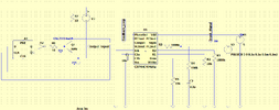
I am trying to design a simple frequency multiplier using CD4046. Since I don't have the ICs I've been trying to simulate on LTSpice. It's a simple circuit with a feedback loop with a D flip-flip which divides the frequency by 2. Therefore, I expect the CD4046 output signal will have its frequency be multiplied by 2.

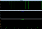
However, it does not work. I am not sure whether the simulation is not working due to the non-official CD4046 model or if the circuit is wrong.

I would really appreciate any help.

Thanks in advance.
 

Attachments

  • Circuit.png
    Circuit.png
    41 KB · Views: 172
  • waveforms.png
    waveforms.png
    44 KB · Views: 147
Connect the D type Q directly to pin 3; the intermediate components are probably messing things up, especially such as the 10 Ohm resistors!

What is the input frequency?
 
Why do you expect that there is such a thing as an official model. Neither Linear Technology, nor Analog Devices EVER made a CD4046. Furthermore, there is no authoritative source for any device models that did not originate from either Linear Technology or Analog Devices. This includes pretty much every BJT, diode, and MOSFET. As you can tell from the change logs, even the official source makes mistakes. Please discard your rose-colored glasses.
 
Connect the D type Q directly to pin 3; the intermediate components are probably messing things up, especially such as the 10 Ohm resistors!

What is the input frequency?
Thanks, I think you are right!

I've tested this design by just wiring VC0out to CompIn and it works. There must be an issue with this intermediate components in the feedback loop. By the way, the frequencies tested ranged from 5Hz to 5KHz.
 
Why do you expect that there is such a thing as an official model. Neither Linear Technology, nor Analog Devices EVER made a CD4046. Furthermore, there is no authoritative source for any device models that did not originate from either Linear Technology or Analog Devices. This includes pretty much every BJT, diode, and MOSFET. As you can tell from the change logs, even the official source makes mistakes. Please discard your rose-colored glasses.
Thanks! at least I've found electro-tech-online.com by searching for this IC model :) and maybe it works in some specific cases.

https://www.electro-tech-online.com/threads/new-spice-model-for-cd4046b-phase-locked-loop-ic.149093/
 
Additionally;
The loop filter values are waaaaay too large. I ignore how the simulation handles this, but…A real world circuit will exhibit a long setting time.
Reduce them by a factor of 10. At least.
 

Latest threads

New Articles From Microcontroller Tips

Back
Top