Continue to Site

Welcome to our site!

Electro Tech is an online community (with over 170,000 members) who enjoy talking about and building electronic circuits, projects and gadgets. To participate you need to register. Registration is free. Click here to register now.

  • Welcome to our site! Electro Tech is an online community (with over 170,000 members) who enjoy talking about and building electronic circuits, projects and gadgets. To participate you need to register. Registration is free. Click here to register now.

OK, here is the whole board. Audio amp. where should I be looking?

Status
Not open for further replies.

fastline

Member
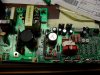
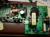
Trying to learn something on this little guy. About as simple as they come I would think. Basically something is dead shorted or shorts once power is applied. In the pics you can find the 2 input AC blades that follow along to the place where the bridge should be and then over to that large PS cap and transformer. There is also 2 mosfets missing There that you can see. I have them off as well.

With the bridge removed, I am not blowing a fuse so I know nothing is shorted on the AC side. When I check continuity at the bridge terminals right now, they are all in the mohms so something has to be energizing and shorting I would think.

Any help or guidance would really be appreciated.
 

Attachments

  • SDC11097.JPG
    SDC11097.JPG
    1.8 MB · Views: 4,428
  • SDC11098.JPG
    SDC11098.JPG
    1.8 MB · Views: 4,371
Last edited:
Please stop making multiple threads on the same question - keep them all in ONE thread.

First thing - do you have a circuit diagram for the unit? - if so post it.
 
What happens if you connect the bridge off the board, and don't connect the outputs of the bridge to the rest of the circuit? Does the bridge output the expected voltage? Does the fuse blow?
 
I have the bridge off of the board and it has tested good on the bench.

So it tested fine hooked up like I said? Did you really try that, or did you power it off a bench AC supply? I am curious how it performs on the actual transformer and fuse setup. BTW - does the transformer output the proper voltage it is rated for? Could the transformer be bad, and only showing an issue under load (blowing the input fuse)?
 
Amplifier without name brand

This is a class D Amp and there are some tricks to know about trouble shooting this type of Amp. this is not like the old class AB amp where use too working on. So pay special attention to wave form. It works like a PWM. Just a hint.
 
Just lost my post..........!!!!

Anyway. Class D, Bash amp. suspecting possibly the transformer but is prettt substantial in build. Previously found a ICL with a pin hole but test good. Circuit used to work perfect and just failed to turn on one day. ICL is still in circuit because it is testing at 10 ohms at room temp and near 0 when warmed up. NTC type. Found a bridged mosfet in the PS and removed both for testing. Still blowing fuse but certain nothing is bridging in the PS and is either the transformer or something in the output side. There are 7 transistors in the outputs but none are testing as shorted with a DMM.

Ideas on what to look for? How to test the transformer? Circuit will blow fuse instantly so thinking something of size is doing this and not a puny 1/4w resistor.

Several pins on the transformer do test 0 ohms to each other but cannot verify that it is bad or designed this way. There is bridging from inputs to outputs. Wish I could find specs for the transformer but doubt that will be found.
 
Last edited:
Amplifier without name brand

Tips, Try separating the Amp from the Pwr Supply by removeing the-/+(HV) source to the outputs, this could be the secondary briged that feeds the power to the outputs, this way you could isolate the short. But before you do that make shure you take a 100W bulb and replace it for a fuse in event that the short persist the bulb will hold the load. Most of the time you have a direct short you might suspect for a shorted Cap. that is in parralel with one of the briged diode. If the short persist look for a shorted PWM IC wich most of the time it could be tl494 or just a bad component.
good luck.
 
UPDATE: So I decided to remove the main PS transformer for inspection and isolation from the output side. It sure seems like there is a problem here but I cannot tell what. I have a transformer with 7 taps on each side for a total of 14. After removing the Xformer, I tested voltages to the xformer and compared those pinouts to the resistance in the xformer. There are 3 pairs on the board that have anywhere from 50-170VDC in which the corresponding pins on the Xformer are near 0 ohms. That is sure to be a problem I would think...I am now looking to see of the voltages should NOT be present there or if possibly the xformer is toast and shorted. I have a hard time believing that BUT I certainly do not see a reason to move forward since it sure looks like any one of these 3 configurations could be considered a hard short.

Could someone shed any light on these types of transformers and how someone might test one?

Also, regarding the large cap in the circuit, is there a better way to test rather than just cap tester? It tested out fine and is not leaking.
 
Amplifier without name brand

well to my knowledge in all my years of experience I've never came across a bad SW PWR Xformer unless it came in to contact with water, they hardly fail so I would discard thinking that the Xformer might be bad, I've seen terroides Xformer go bad all the time. But not this kind. Look for a bad components, never underestimate any component, all are considered to go bad. Most of the time try pulling them out completly and measure them outside if possible.
 
Here is the deal. I have chased and chased and looking VERY hard at a small daughter board that certainly runs the mosfets that failed as well as the origin of the voltage that I am seeing at the transformer pins. I am not sure if the voltage I see to the transformer will drop with a load or not. Not sure how I might test that just yet. In looking at this daughter board, it is filled with resistors, zeners, and 1 TO-92 size transistor, and a few very small yellow bubble looking devices that I can not determine. One has a 472 on it but that is it. I have a hard time believing this little board can handle 600w to blow the fuse without burning up.

I tested every single component on the board for a short. Nothing is dead shorted but seeing a couple in the 1K ohm range in circuit. No more info without removing. I hear zeners like to fail shorted in which these are not. Hmmm.....Large PS cap is out, xformer is out. indication is that if I reinstall the xformer, the fuse will blow because I will be bridging the short BUT I am not sure if the voltage I am seeing is really even a problem. Think I will add a resistor in a test circuit and see what happens. Guess I would apply for a few sec and see if I get any heating at all to determine if there is current there.
 
Nother update..

I connected each pair of pins to the transformer 1 by 1 that were showing voltage along with very low resistance at the xformer. In each instance, there was zero amperage increase. I monitored the input current will adding bridged across them.
Bottom line is I think the PS side is just fine and that daughter board as well is fine. I am going to start looking at the output stages now. I really want to pull all the transistors off and give it a go because that seems a VERY common mode of failure. None are testing shorted but cannot test leakage in circuit..
 
I had a similar problem with my subwoofer (Athena AS-P4100). It has the same circuit as yours, even the transformer model number. I found out the transformer is the problem. However, I do not have the transformer specifications. I tried to contact the transformer manufacturer, Indigo Electronics Canada (as written on the transformer and power supply PCB) but the telephone number seems to divert to a fax machine. Please give an update if you found out the transformer output voltage levels.
 
Hi,

I'm fighting with the same sh*tty circuit, only from a JAMO SUB650... Clearly some kind of chinese crap. Anyhow, there are two amps working in bridged mode and are straightforward AB class with a pair of mosfets on the output.
The PSU its a little bit more tricky... There is the input converter which is an self oscillating half bridge circuit. It works immediately when you switch on the board and spits out some 80Vdc at the main smoothing capacitor! And here is where the fun begins, there is a kind of switching circuit - I traced down part of the circuit - which is connected somewhat unusually. What happens is, that the amplifiers get the full supply voltage instead of getting a variable supply according to the output power requested...
I replaced the small IC on the daughter board - UC3842A but still nothing. There are two fat resistors 150ohm 4Watt each, used to achieve a virtual ground - you see, the amps are powered with single ended voltage - that start to smoke since they are not able to dissipate the power delivered from the main PS. They are connected in series and the mid point is the virtual ground for the rest of the low power amp circuit. Being 300ohm connected straight across 80Vdc they should dissipate some 22Watts(remember the two are 4Watt/each). So this is the clue to me, that the switching circuit(yess indeed there is a large inductor...), somehow LOWERS the supply to the output amps, when full power is not needed...
Of course I contacted Jamo and of course they very politely told me to bug-off...

Jamo used to be a serious manufacturer but not anymore it seems.
 
Last edited:
I can't imagine 1 mA damaging anything and so you can make a curve tracer by putting AC into the power supply input through a high value resistor such that you get less than 1 mA peak into the amp and you monitor the waveform across the amp to get its V-I curve. IIRC this is how the Huntron Tracker worked.
 
Status
Not open for further replies.

Latest threads

Back
Top