Continue to Site

Welcome to our site!

Electro Tech is an online community (with over 170,000 members) who enjoy talking about and building electronic circuits, projects and gadgets. To participate you need to register. Registration is free. Click here to register now.

  • Welcome to our site! Electro Tech is an online community (with over 170,000 members) who enjoy talking about and building electronic circuits, projects and gadgets. To participate you need to register. Registration is free. Click here to register now.

Noise in ramp output?

Status
Not open for further replies.

pavjayt

Member
Hi,

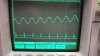
I have a board that outputs a ramp signal at 30Hz as per the attached schematic. when I zoom into the signal at about 100mV scale, I can see this sinusoidal noise at my clock frequency. The digital inputs for AD7533 are from a 74VHC4040 IC and my clock frequency is at 15KHz.

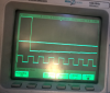
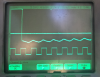
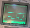
The attached picture (Pic1) shows the noise at 100Mv amplitude scale and lower channel3 shows the clock. Pic2 shows it at a zoomed out scale of 5V. I am sure there are many factors that could result in this kind of output, but would like to know if there is something that's basic that I am not doing right here.

Let me know if I can provide anymore details to better understand the problem.

thanks
 

Attachments

  • Pic1.jpg
    Pic1.jpg
    1.2 MB · Views: 204
  • Pic2.jpg
    Pic2.jpg
    1 MB · Views: 200
  • ramp.png
    ramp.png
    58.6 KB · Views: 227
Usually such digital noise in an analog signal indicates that there's a problem with improper separation between the analog and digital grounds and/or with the layout of the circuit.
You should have a split digital / analog ground plane, and they should only be connected together at one spot, generally near where there is circuitry with a digital input and an analog output (such as a D/A converter).
Also the digital chips should be in a separate area from the analog chips.

How is your board constructed?
Does it have separate analog and digital grounds?
Are the analog and digital chips separated?
 
I am having trouble following your drawings.
Your clock is at 15khz.
Normally, within the op-amp section, there is a low pass filter. The goal is to remove frequencies at 15khz and above.
 
I haven't separated the grounds, I kept it as a continuous ground this time around. Not sure if it helps, but I have attached a screenshot of the design. Could there be any other modification I can do to eliminate this noise?

U6 - HC4040
U7 - AD7533
U10 - AD712
U11 - LM6181

Bottom plane is ground plane.

For next time I am gonna keep the grounds separate.

thanks
 

Attachments

  • digital.png
    digital.png
    952 KB · Views: 215
Last edited:
Eliminating noise is a built design can be difficult and require a lot of detective work.
You might try rolling off the response of the op amp as much as possible as Ron suggested, just to the point that the sawtooth isn't distorted.
See if you can trace the noise.
For example, do you see it on the VREF line (U7-15)? If so you might try adding a decoupling capacitor there.
Is it possible to cut through the ground plane to isolate the section containing the analog parts?
 
I looked at another DAC for making high speed waveforms. They added a filter after the DAC. Here is the response of the filter. In your case F=15khz.
upload_2015-9-5_8-35-14.png

The natue of the DAC will make noise at the switching frequency.
 
Without any filter after the output of the DAC, I would have expected to see a series of steps, a "staircase" output from the DAC.

I am confused that you are seeing a sinewave on the output of your DAC.

I also see that you have the scope set to "averaging", what do you see when averaging is turned off?

I have this feeling that the output of your DAC is not a staircase as I would expect.

As ronsimpson said, you need a lowpass filter after the DAC to remove the staircase effect, which in the frequency domain will be seen as harmonics.
Remove the harmonics and you smooth out the staircase.

JimB
 
Looks like I found the source of the noise, its the ALD7556 IC that I have in digital section of my board. I removed it and the nosie is gone in my ramp output, as soon as I soldered it back, I see it again. Not sure what steps I should take to reduce this as I need ALD7556 too in my design.

Attached pictures are the screen shots of the signal at different conditions.

Thinking of going with LM556 IC rather than ALD7556, any suggestions?

Edit: Upon further inspection, I found out that this ground noise with spikes is appearing whenever I connect the output of ALD7556 which is in digital section to OPA875 multiplexers in analog section.

thanks
 

Attachments

  • GND and Ramp without ALD.png
    GND and Ramp without ALD.png
    1.1 MB · Views: 166
  • Ramp with ALD7556.png
    Ramp with ALD7556.png
    1.1 MB · Views: 247
  • GND with ALD7556.png
    GND with ALD7556.png
    559.8 KB · Views: 173
Last edited:
Status
Not open for further replies.

Latest threads

Back
Top