martianent
New Member
I have been looking for a while into building my own custom digital instrumentation for my car. Mostly because I don't like the costs associated with the pre-built stuff ($400 for some gauges! And there is a full set out there for $600!) and the fact that there aren't any drop-in clusters available for my car.
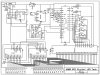
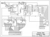
I bought a book, called Building Your Digital Dashboard, Volume 1 by a guy by the name of Christian Forget, who runs a site and company that sells conversion parts for Knight Rider KITT clone cars, called Jupiter Electronics. I have the schematics and parts lists for 5 out of the 6 instruments, but I feel that the tach could be a little better, seeing as how it only shows 3 digits. I also noticed, while coming up with my schematics, that some parts of the Jupiter design seem to be incorrect, namely the multiplexing on the LM3914N IC's, which he has in parallel for the signals instead of connecting pin 9 of the first 3914 to pin 1 of the next. My plan, instead of using the CA3161E and 3162E 3-digit ADC and driver in the schematic for the LED numerical display, is to replace them with a Maxim ICM7135 and ICL7212. I have drawn up a schematic in ExpressSCH and need someone to look it over before I buy and fry these expensive chips and the board that goes with them ($66 by my count). Can someone point out to me any mistakes I may have made before I get too far into Express PCB? I think I followed the datasheets for the LM3914Ns, ICM7135, ICL7212, and the others properly, but I'm hoping someone with a practiced eye can tell me if I did or not. I'm not a novice when it comes to soldering, so putting these together should be easy when I get the boards made and the components together.
Oh, and the reason the SCH is so squished is because I only had an 8.5x11" space to work with. I know I needed more room.