Continue to Site

Welcome to our site!

Electro Tech is an online community (with over 170,000 members) who enjoy talking about and building electronic circuits, projects and gadgets. To participate you need to register. Registration is free. Click here to register now.

  • Welcome to our site! Electro Tech is an online community (with over 170,000 members) who enjoy talking about and building electronic circuits, projects and gadgets. To participate you need to register. Registration is free. Click here to register now.

need correction about linear regulator circuit

Status
Not open for further replies.

zhi_yi

New Member
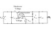
hi there, please help me, i got a little confused with this circuit, please give a correction, is it from the circuit would be like this? if the load increases, then the current flow through the low would be decreased because of the capacitor would be discharging its charge slowly (Vc = Vload = Vin.e^-t/RC), and the voltage through the load would just fall a little, so the difference between Vref and the output divider would just fall a little too, so the output from the error amplifier would not be so high, so, the headroom voltage would be lower, its mean that the resistance in collector emitter is low, and will providing more current through the load, and if the load is decreased, for example we short the two terminal of the capacitor, then, the load current would be exceeded, and the output voltage will fall, so, the voltage in the divider output that connect to the inverting will drop too, so, the difference between the Vref and the Voltage divider would be high, and the output from the error amplifier will be high too because Vout = A(V+ - V-), and it would makes the Collector emitter voltage rise, and its mean that the resistance in the collector emitter would be rise too, and limit the exceeded current to flow to the load, is it true? please correct me... :(

thank you very much :)
 

Attachments

  • load_prob.jpg
    load_prob.jpg
    10.8 KB · Views: 598
Hi Zhi,
Never mind the capacitor when you analyse a voltage regulator.

1) The load current increases and causes the output voltage to drop.
2) The 2-resistors voltage divider feed the dropped voltage to the inverting input of the error amp.
3) With the voltage at the inverting input of the error amp too low compared to the reference voltage voltage at its non-inverting input, the output of the error amp goes high just enough to turn-on the transistor more to raise the output voltage to what is required.

If you short the output, the error amp will fully turn-on the transistor. Nothing limits the current so the transistor might overheat or be damaged from too much current through it.
 
A possible way to add a current limiter:
 

Attachments

  • load_prob_156.jpg
    load_prob_156.jpg
    9.6 KB · Views: 568
thank you very much :)

is it the function of current limitter is to protect if the excessive current flow to the load?

please tell me how do that current limitter circuit work?
 
zhi_yi said:
is it the function of current limitter is to protect if the excessive current flow to the load?
What if the load is shorted?
What will happen to the transistor with too much current through it?
What will happen to the Vin source with too much current from it?


please tell me how do that current limitter circuit work?
A current sense resistor has been added in series with the load. What happens across it when the current is too high?
 
okay.. thank you :) i like the way you answer my questions :)

i understand it now, but there is something make me confused in the current limitter, what is the function of the diode in parallel with the potentiometer?
 
Status
Not open for further replies.

Latest threads

New Articles From Microcontroller Tips

Back
Top