Continue to Site

Welcome to our site!

Electro Tech is an online community (with over 170,000 members) who enjoy talking about and building electronic circuits, projects and gadgets. To participate you need to register. Registration is free. Click here to register now.

  • Welcome to our site! Electro Tech is an online community (with over 170,000 members) who enjoy talking about and building electronic circuits, projects and gadgets. To participate you need to register. Registration is free. Click here to register now.

my superregen needs perfection

Status
Not open for further replies.

mstechca

New Member
I have looked at: http://techlib.com/electronics/regen.html
and found this regen circuit:

**broken link removed**

Some of the differences between it and my circuit are the following:

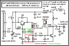
#1. In my circuit A tank circuit is connected between emitter and ground. instead of a resistor and capacitor, because I want more gain.

#2. the capacitor between collector and emitter is variable in my circuit, and the capacitor connected between emitter and ground is also variable.

#3. Both inductors in my circuit are 0.1uH, and the capacitors described above will always be the same. I am gang-tuning them through varactors.

#4. the 365pF tuning cap is not used in my circuit. and my antenna is connected to ground.

I think my problems are due to bad biasing.

For an optimal superregen, should I bias the transistor so that when nothing triggers the base, the voltage at the base is barely at the transistor turn-off point (< 0.65V?)

I find that the more voltage dividers I use in my circuit, the better the quality of the output.

I want to modify the 10K resistor in the circuit shown above, as well as the 100K pot, and the 2 100K's next to it. I want to condense it to three resistors.

Because there are two connection points between the new three resistors in series, what voltage or current should I use at these connection points.

I want acceptable volume with quality reception.

and yes, in all my experimenting, I can still pick up CHTV. :wink:

I do think that incorrect voltage and/or incorrect current can lead to failure.
 
mstechca said:
#1. In my circuit a tank circuit is connected between emitter and ground. instead of a resistor and capacitor, because I want more gain.
That is the problem with your circuit.
The voltage gain of a transistor is defined as the ratio of the impedance at its collector to the impedance at its emitter.
Your circuit has the high impedance of a parallel tuned circuit at its emitter so has very little gain. Every other regen receiver has a very low impedance capacitor at its emitter for very high gain.

#4. my antenna is connected to ground.
Really?

I think my problems are due to bad biasing.

For an optimal superregen, should I bias the transistor so that when nothing triggers the base, the voltage at the base is barely at the transistor turn-off point (< 0.65V?)
The circuit you started with was a super-regen that had an ultrasonic squegging oscillator built-in. It would ramp up its gain until it began to oscillate and the beginning of oscillation would cut it off so it ramped up its gain again over and over. The "super" parts kept the transistor's gain at max automatically. You changed the circuit so much that it isn't super anymore and requires a manual bias "sensitivity" control like the recent SW-regen circuit you posted.

and yes, in all my experimenting, I can still pick up CHTV. :wink:
CHCH-TV changed their name to CH-TV and don't say their transmitted power anymore. I think its audio is transmitted with at least 100,000W so since you are so close to the transmitter you should be able to pick it up with only a short piece of wire sticking out of your ear! :wink:
 
AG, we had this discussion once before - the emitter of the transistor is low impedance. If the other components attached to the emitter were also low impedance, this would decrease the gain, not raise it.

I tried to get this circuit to oscillate (and squegg) in a simulation,but it would not even oscillate, much less squegg. I did get it to oscillate by reducing the collector resistor to zero and increasing the emitter resistor to at least 8k. I think this is a case where simulation fails, perhaps due to the simplicity of the models. I'm not motivated to build it and see if it actually works.
 
Ron H said:
AG, we had this discussion once before - the emitter of the transistor is low impedance. If the other components attached to the emitter were also low impedance, this would decrease the gain, not raise it.
I know, it is an oscillator, not an amplifier. I was discussing an amplifier so I would need to get into a discussion of how the low impedance at the emitter loads down the tuned circuit there so much, but then how the positive feedback causes the emitter to be a high impedance current source.
It is best to have the tuned circuit at the high impedance collector.
 
audioguru said:
Ron H said:
It is best to have the tuned circuit at the high impedance collector.
No argument there.

BTW, I made the assumption that this was supposed to be a superregen, because that's what mstecha has made a career of. I reread his post and the referenced website and discovered that it's a regen. I did get it to oscillate in the sim by setting a small minimum step size. It's no wonder it won't squegg - it's not supposed to. :oops:
 
Hi Ron,
Here is the website that has MStechca's 1st super-regen receiver:
www.tricountyi.net/~randerse/superrgn.htm
I marked its "quench oscillator's" parts and a possible damper for it. If it doesn't oscillate then increase the value of its 7pF cap.
 

Attachments

  • superrgn.gif
    superrgn.gif
    10.1 KB · Views: 694
Ron H said:
BTW, I made the assumption that this was supposed to be a superregen, because that's what mstecha has made a career of.

He keeps calling it a 'super-regen', but his random changes stopped it being one a LONG time ago :lol:
 
I forgot that a regen receiver detects AM, not FM. So in order for it to detect FM it must be tuned to a side of the signal for it to "slope detect" it. Since it is tuned to a side instead of at the peak then the signal strength is reduced.
 
Couldn't I declare the tank circuit in the emitter as a band-reject filter?

Take a look at the picture below. The circuit won't work if you try it (that is obvious).

but it shows how I am using the arrangement shown by tpub.com.

Here is their original image:

**broken link removed**

Notice how I am using the "band reject" portion connected to my emitter?
and the other two LC components are "band pass". I am using 2 LC components for better filtering, and I am gang-tuning them through varactors.

But.... In the circuits I see, Isn't a quench circuit just a low-pass filter, because in the 1st circuit shown, and in Rick Andersons circuit, they connected a capacitor to a resistor, and connected the center of it to the inductor. The difference between the two circuits is the polarity given to the resistor.

...but his random changes...
Nigel, Welcome to True, Hands-on Experimentation! :lol:

I tried to get this circuit to oscillate (and squegg) in a simulation,but it would not even oscillate,
Ron, We are dealing with VHF here. Well over 145Mhz. I doubt any software can simulate it.
 

Attachments

  • bpf.gif
    bpf.gif
    4.7 KB · Views: 651
Ron, We are dealing with VHF here. Well over 145Mhz. I doubt any software can simulate it.
It's just the opposite. Simulation is just arithmetic. A simulator doesn't care if the frequency is a bazillion hertz, or the capacitance is a micro-femptofarad. It's just numbers.
In fact, in my job we simulate with femptofarads (look that up in your Funk & Wagnalls) and gigahertz every day. We couldn't make parts that work, otherwise.

EDIT:
I was simulating the circuit as designed. With the values in the schematic, it's an AM brodcast band receiver, ~500kHz-1.5Mhz.
 
mstechca said:
Couldn't I declare the tank circuit in the emitter as a band-reject filter?
It would if the transistor is an amplifier, but the transistor is an oscillator so the "band reject" filter selects the oscillator's frequency.

Notice how I am using the "band reject" portion connected to my emitter?
Therefore the oscillator oscillates at its tuned frequency.

the other two LC components are "band pass".
They are supposed to connect to the input of another RF amplifier. Your circuit doesn't have one. Where do they connect the band pass RF frequencies to? To an audio amp? To the RF-grounded supply?

I am using 2 LC components for better filtering, and I am gang-tuning them through varactors.
Their frequencies don't match because the capacitance of the transistor is across the series one. Each tuned circuit will also have different stray capacitance.

Isn't a quench circuit just a low-pass filter
No. The capacitor to ground charges when the transistor begins to oscillate and a signal is received at its frequency. When its voltage is high enough, the transistor gets cutoff and stops oscillating. Then the capacitor discharges into the resistor until its voltage is low enough that the transistor starts conducting and begins oscillating again. The choke is a high impedance to RF so the capacitor doesn't ground the emitter. The capacitor, resistor and transistor's current determine the frequency of the ultrasonic quenching.

It quenches the oscillation so that hopefully the transistor remains on the edge of oscillating so its gain is very high.

...but his random changes...
Now you have an RF oscillator instead of a super-regen, and you have two bandpass circuits at different frequencies.
 
They are supposed to connect to the input of another RF amplifier. Your circuit doesn't have one. Where do they connect the band pass RF frequencies to? To an audio amp? To the RF-grounded supply?
no, it goes to the input of my amplifier arrangement I showed you weeks ago in another post, and it is capacitor coupled.

Their frequencies don't match because the capacitance of the transistor is across the series one. Each tuned circuit will also have different stray capacitance.

So maybe that's why I'm not receiving 100% perfection in my reception. I knew you guys could give me A decent answer :!:

But I am lucky I can get about 99% pure reception because the transistor I am using is a Pn3563.

I would rather add the equivalent capacitance across the band-reject filter to compensate for the transistor capacitance than to add another Pn3563 because capacitors use less space.

How do I determine the capacitance of the transistor if I were to use the emitter and collector pins?
 
mstechca said:
audioguru said:
They are supposed to connect to the input of another RF amplifier. Your circuit doesn't have one. Where do they connect the band pass RF frequencies to? To an audio amp? To the RF-grounded supply?
no, it goes to the input of my amplifier arrangement I showed you weeks ago in another post, and it is capacitor coupled.
An RF bandpass filter doesn't do any good when it goes to an audio amp.

But I am lucky I can get about 99% pure reception because the transistor I am using is a Pn3563.

I would rather add the equivalent capacitance across the band-reject filter to compensate for the transistor capacitance than to add another Pn3563 because capacitors use less space.

How do I determine the capacitance of the transistor if I were to use the emitter and collector pins?
You must GUESS. They don't have a typical value, they don't even have a minimum value. You probably can't measure such a low capacitance.
 

Attachments

  • pn3563.png
    pn3563.png
    27.4 KB · Views: 550
Status
Not open for further replies.

Latest threads

New Articles From Microcontroller Tips

Back
Top