littletransistor
New Member
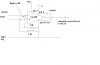
audioguru said:Your circuit is missing the 100uF capacitor from pin 5 to pin 4. The inputs are not balanced without it and then they pickup and amplify a lot of mains hum.
Also, you don't show a wire called Ref from pin 5 that connects to the patient's leg. Without it then the inputs are not biased.
Measure the output DC voltage again. It should be close to half the supply voltage. What is the supply voltage?
Okay - I'll connect the 100uF cap to the 4, and 5, and also Ref to my leg.
Update: Yes - the DC output is already around half of the supply voltage - 3.85 - 3.95V. But still, it's a little bit more or less than the 0.75V difference.
edit: well, I suspect that the computer of mine is playing tricks on me - apparently those line-in inputs should not be directly connected to my ECG machine. I read in another ECG kit that they added the line-in driver or a modulator thingy inside to make it properly work! :eek If so, I might need to go to my school's lab and try it out on an oscilloscope instead.
")
Last edited: