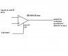
Ordinary opamps have a input offset voltage of up to 10mV. The gain of 1785 would amplify an input offset voltage of only 1.85mV causing the output to be saturated against the positive power supply voltage or to ground.
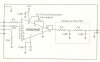
An instrumentation amplifier has very low input offset voltage.
If you used opamps that have very low input offset voltage then the circuit should work.
I don't know if patients are grounded.
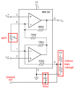
An instrumentation amplifier has very low input offset voltage.
If you used opamps that have very low input offset voltage then the circuit should work.
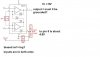
I don't know if patients are grounded.
")