Continue to Site

Welcome to our site!

Electro Tech is an online community (with over 170,000 members) who enjoy talking about and building electronic circuits, projects and gadgets. To participate you need to register. Registration is free. Click here to register now.

  • Welcome to our site! Electro Tech is an online community (with over 170,000 members) who enjoy talking about and building electronic circuits, projects and gadgets. To participate you need to register. Registration is free. Click here to register now.

Mc1496

Status
Not open for further replies.
after all discussions about SSB. just to know and have more info about modulation i would like to know:
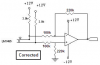
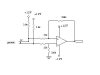
how it is possible to make a SSB from a AM or DSB circuit like the above circuit?
i learned how it is possible making AM and DSB by modulator IC's but i am not sure how it is possible to get a SSB from these kind of modulators,
i am thinking that this is possible by a filter, a high or low pass filter to get upper or lower sidband but don't know what kind of filtersand how?
 
The DSB circuit that you attached has a suppressed carrier. So your receiver must re-insert a carrier into the received signal for the modulation to be properly detected. The re-inserted carrier must be exactly the same frequency as the original carrier.
You don't need DSB, the AM that you had is the same except this DSB circuit suppresses the carrier to save transmitting power.

Similarly, you don't need SSB. I made some SSB circuits for voice scrambling and they worked perfectly. I used a switched-capacitor Butterworth lowpass filter IC to filter out the unwanted sideband. With a quartz crystal for the transmit and receive carriers, the unscrambled sound was perfect and the scrambled sound was completely unintelligible.
 
audioguru said:
The DSB circuit that you attached has a suppressed carrier. So your receiver must re-insert a carrier into the received signal for the modulation to be properly detected. The re-inserted carrier must be exactly the same frequency as the original carrier.
You don't need DSB, the AM that you had is the same except this DSB circuit suppresses the carrier to save transmitting power.

Similarly, you don't need SSB. I made some SSB circuits for voice scrambling and they worked perfectly. I used a switched-capacitor Butterworth lowpass filter IC to filter out the unwanted sideband. With a quartz crystal for the transmit and receive carriers, the unscrambled sound was perfect and the scrambled sound was completely unintelligible.


ok, today i got more time to read a paper about AM modulation.
now i understand why don't need for a SSB and i am aware about the DSB problems,
i said before that i like to learn modulation so wanted to know the ways of SSB creating and i found the way by reading the paper,
dont want to build it with SSB modulation but just like to know what kind of IC you used as filter? such as i know it is possible making a filter by few caps, resistors and selfs(coils), i never seen a IC used as a filter but i think you use from an OP AMP, am i right?
 
i have a quetion about AM,

after reading a paper and some of other brief topics about amplitude modulation i noticed that we need a big bandwidth, at least 20kHz for AM and DSB and 10kHz for SSB,
before reading the story i thought that when we use from a carrier at a specific freq and modulate it with an audio the output changes ONLY in the AMPLITUDE and it has a constant freq that is equal with carrier freq, so the bandwidth would be narrow.
can a person direct me why this is not true?
i think i know the answer but i am not sure.
 
You need to learn more about AM so that you understand about when it is modulated then an upper sideband and a lower sideband are formed that use bandwidth.

When I made a SSB voice scrambling circuit I used a switched-capacitor Butterworth lowpass filter IC to remove (filter out) the unwanted sideband.
National Semi used to make many excellent switched capacitor filter ICs but not now. Maxim make some now.
 
The Wikipedia entry on amplitude modulation has a good description of the mathematical derivation of the sidebands, if you have the background to understand it.
 
audioguru said:
The modulator IC isn't perfect. A little amount of the modulating signal goes to its output.
.


yes audioguru, i just realized that the problem about having part of unmodulated sound in the output is because of 1496 itself.i found out that i can remove it if i use my chip as a balanced output,
can you let me know how can i use the chip as a balanced output?
i think it is possible using an OP AMP or a transformer with a tap, am i right?

thanks.
 
Ron:
tonight i reread the whole of this thread, somewhere you said "If you are transmitting ultrasonically, channel bandwidth is unimportant. "

as we know an ultrasonic transducer has a sharp resonant at 40kHz
so it should not be so good for my job, am i wrong?
i know that the carrier is 40kHz but i think i will have something much more than 40kHz at the output of trasducer?!
 
epilot said:
Ron:
tonight i reread the whole of this thread, somewhere you said "If you are transmitting ultrasonically, channel bandwidth is unimportant. "

as we know an ultrasonic transducer has a sharp resonant at 40kHz
so it should not be so good for my job, am i wrong?
i know that the carrier is 40kHz but i think i will have something much more than 40kHz at the output of trasducer?!
I'm really not very knowledgeable about ultrasonic transducers. What I meant was, minimizing the amount of bandwidth used is unimportant. See this site for the advantages (and some disadvantages) of SSB over DSB. This article was written with RF transmission in mind. Perhaps some of the advantages would be important enough to try using them with ultrasonic transmission. If your transducer has narrow bandwidth, maybe that would be reason enough to go through the hassle of regenerating the carrier. I don't know.
 
epilot said:
yes audioguru, i just realized that the problem about having part of unmodulated sound in the output is because of 1496 itself.i found out that i can remove it if i use my chip as a balanced output,
can you let me know how can i use the chip as a balanced output?
i think it is possible using an OP AMP or a transformer with a tap, am i right?
A transformer is expensive. Look-up Opamp Differential Amplifier in Google. Then both outputs of the MC1496 connect to both inputs on the differential amplifier.
 
audioguru said:
A transformer is expensive. Look-up Opamp Differential Amplifier in Google. Then both outputs of the MC1496 connect to both inputs on the differential amplifier.

but i think there is a problem using an OP AMP:
an OP AMP can not be used for ULTRASONIC(please be noticed the output of OP AMP must go to more than 40kHz)
so i think the only way is using a small transformer?
i am not sure what kind of transformer is the best choice?
 
Last edited:
epilot said:
but i think there is a problem using an OP AMP:
an OP AMP can not be used for ULTRASONIC(please be noticed the output of OP AMP must go to more than 40kHz)

Many opamps are fine at 40KHz, just choose them accordingly.

so i think the only way is using a small transformer?
i am not sure what kind of transformer is the best choice?

If going the transformer route you need a specific transformer for the job, which you will most probably have to wind your self?.

A long time back in this thread I suggested ignoring the transducers, and connecting the modulator output via wires to the demodulator - have you ever done this?. There seems little point in worrying about opamps or transformers if the basic circuit doesn't work in the first place?.
 
Nigel Goodwin said:
Many opamps are fine at 40KHz, just choose them accordingly.


If going the transformer route you need a specific transformer for the job, which you will most probably have to wind your self?.

A long time back in this thread I suggested ignoring the transducers, and connecting the modulator output via wires to the demodulator - have you ever done this?. There seems little point in worrying about opamps or transformers if the basic circuit doesn't work in the first place?.

i have 741, LF411, LF351, LF356 in my hands, what is your idea about using 741 as a differential op amp according to this pic?

Nigel,
i modified the modulator circuitry and could get a good result from its output
and my oscilloscope shows that the circuit works fine except that small sound that passes from the input of the chip to its output,
i have not tried the reciever part yet and i must remove that sound to try the reciever part using another 1496 too.
 

Attachments

  • untitled.JPG
    untitled.JPG
    33.3 KB · Views: 193
Last edited:
epilot said:
i have 741, LF411, LF351, LF356 in my hands, what is your idea about using 741 acording to this pic?

A 741 is a really ancient VERY low spec device, OK 30 years ago, but you should have stopped using them over 20 years ago!.

I'm sure Audioguru will make opamp suggestions, he's the man with all the datasheets at his fingertips! ;)

Nigel,
i modified the modulator circuitry and could get a good result from its output
and my oscilloscope shows that the circuit works fine except that small sound that passes from the input of the chip to its output,
i have not tried the reciever part yet and i must remove that sound to try the reciever part using another 1496 too.

Then do that part NOW, there's no point messing around with the ultrasonic part is the rest of it doesn't work - once you have it working via a simple piece of wire (bearing in mind that will have a far higher bandwidth than the ultrasonics will), you can then add the ultrasonics part.

I'm still highly dubious about the entire premise of this scheme?.
 
Like most modern opamps, the LF351 has a power bandwidth to above 100kHz. The old 741 has a max of only 9kHz.

Your opamp differential amplifier has its input pins reversed, is not balanced sincethe values of the 330k and 390k resistors are different and has way too much gain (maybe the modulation level is too low).

I corrected the schematic:
 

Attachments

  • opamp differential amplifier.PNG
    opamp differential amplifier.PNG
    12.1 KB · Views: 186
audioguru said:
Like most modern opamps, the LF351 has a power bandwidth to above 100kHz. The old 741 has a max of only 9kHz.

Your opamp differential amplifier has its input pins reversed, is not balanced sincethe values of the 330k and 390k resistors are different and has way too much gain (maybe the modulation level is too low).

I corrected the schematic:

i used LF351 as a differential amplifier like your scheme but i have that sound yet!!!
it is unclear now but no weaker?
 
Do you have a 100uF supply bypass capacitor? Maybe the audio is modulating the power supply voltage if the capacitor is missing.
 
audioguru said:
Do you have a 100uF supply bypass capacitor? Maybe the audio is modulating the power supply voltage if the capacitor is missing.

can you explain your mean clearly please?
 
Supply bypass capacitors are connected from +12V to 0V and from -12V to 0V. They keep the power supply voltages from bouncing up and down with the signal, if the supplies are disposable batteries or other voltage sources with internal resistance.
 
Status
Not open for further replies.

Latest threads

New Articles From Microcontroller Tips

Back
Top