Continue to Site

Welcome to our site!

Electro Tech is an online community (with over 170,000 members) who enjoy talking about and building electronic circuits, projects and gadgets. To participate you need to register. Registration is free. Click here to register now.

  • Welcome to our site! Electro Tech is an online community (with over 170,000 members) who enjoy talking about and building electronic circuits, projects and gadgets. To participate you need to register. Registration is free. Click here to register now.

Mc1496

Status
Not open for further replies.

epilot

Member
hello friends,

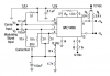
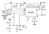
i want to make an AM modulator using MC1496,
my problem is that the IC needs -8V for pin 14 while the supply is 12V and i don't know how to provide the voltage for this pin,
regarding to the datasheet can anyone help me find a solution for this problem?
https://alldatasheet.com/datasheet-pdf/pdf/12005/ONSEMI/MC1496.html
thanks for any help.
 
I don't think you can change the +12V power pully to a negative supply, but you can use a micro transformer with centretapped output combined with a diode bridge and then use the negative output, sending it through a LM317 (can be used for negative supplies) + some capacitors.

Hope it can do it
 
Voltage pump IC's such as the ICL7660 and LT1054 will both take a positive
voltage and with a few external components give a negative voltage with
respect to ground out.
 
If you can handle AC coupling for your modulating signal, this should work down to around 20Hz.
 

Attachments

  • LM1496 modulator.PNG
    LM1496 modulator.PNG
    14.3 KB · Views: 1,077
but can i ground this pin?

i don't like to use from extra components in the circuit for simlified,

i am in doubt, what will happen if i use from a square carrier wave oscillator rather than a sine wave?
 
Ron H said:
If you can handle AC coupling for your modulating signal, this should work down to around 20Hz.

Thanks Ron for your reply,

i want to give the IC a 40kHz as a carrier and a 50Hz to 15kHz signal as modulating signal.

today i spent alot of my time to find a solution for pin 14 of 1496 and a good matched carrier oscillator but there was no success with google!

don't know why there is no solution from IC company!
 
epilot said:
Thanks Ron for your reply,

i want to give the IC a 40kHz as a carrier and a 50Hz to 15kHz signal as modulating signal.

today i spent alot of my time to find a solution for pin 14 of 1496 and a good matched carrier oscillator but there was no success with google!

don't know why there is no solution from IC company!
I have used 1496's (many years ago). The modification I posted should work for that range.
 
epilot said:
Thanks Ron for your reply,

i want to give the IC a 40kHz as a carrier and a 50Hz to 15kHz signal as modulating signal.

today i spent alot of my time to find a solution for pin 14 of 1496 and a good matched carrier oscillator but there was no success with google!

don't know why there is no solution from IC company!

From this, are we to assume you're wanting to send audio via an AM modulated ultrasonic carrier?, perhaps super-imposed on an IR LED?.

If so?, a 1496 seems rather overkill!.
 
Nigel Goodwin said:
From this, are we to assume you're wanting to send audio via an AM modulated ultrasonic carrier?, perhaps super-imposed on an IR LED?.

If so?, a 1496 seems rather overkill!.

Hello Nigel, yes i want to modulate part of audio frequency with a carrier(i prefer 40kHz as carrier)

i can not understand you by "super-imposed on an IR LED"

i am working on 1496 and if i can nopt handle it i'll go for AD633 chip.

i'll try Rons way at first and see what will happen.

i lke to know what will happen if the carrier becomes a square wave
 
epilot said:
Hello Nigel, yes i want to modulate part of audio frequency with a carrier(i prefer 40kHz as carrier)

i can not understand you by "super-imposed on an IR LED"

Just that IR is often modulated at 38/40KHz, presumably as a left over from the old ultra-sonic days - so you may have been doing either.

i am working on 1496 and if i can nopt handle it i'll go for AD633 chip.

i'll try Rons way at first and see what will happen.

i lke to know what will happen if the carrier becomes a square wave

I wouldn't expect it to make any difference to the modulation, my main concern is the entire premise of the scheme! - I suspect quality is going to be very poor, and your frequency range is highly optimistic.

What exactly are you trying to do?, and over what range?.
 
Nigel Goodwin said:
Just that IR is often modulated at 38/40KHz, presumably as a left over from the old ultra-sonic days - so you may have been doing either.


I wouldn't expect it to make any difference to the modulation, my main concern is the entire premise of the scheme! - I suspect quality is going to be very poor, and your frequency range is highly optimistic.

What exactly are you trying to do?, and over what range?.

well, i am involving with making a circuit to send audio or part of audio via ultrasonic as a carrier and another circuit as receiver will receive these waves(via ultrasonic too) and demodulate it and then propagate it via speaker.
the main aim is to learn AM and ultrasonic togather
 
Ron,
i Modified the circuit like your circuit,

then i used from UM66 musical IC as modulated input signal and a 40kHz carrier wave made by a 555 IC,
the output(pin 6) shows about 80kHz!!!

i can not see any increase in amplitude with my scope!!!

i am not sur if i must see any increase at the moment,
perhaps i must remove one Side band at first?

do i need for dc offset..?

i'll try to read more about AM.
 
WELL,now i think the problem is the "square wave" made by 555 ic as carrier.
i have to convert it to sine wave,
i don't know any way to convert the 555 square wave into sine wave, so i must make a sine wave generator.

i want to build this: **broken link removed**
but because it uses a lamp to generate sine waves so i am not sure if it is stable and suitable for my job?
what is your idea friends?
 
You don't need a sine wave. You only need about 500mV p-p for the carrier, but make sure it is SQUARE (50% duty cycle). You can get 50% from a 555, but not with the "standard" astable circuit.
The modulating signal (audio) will be clipped if you exceed 2V p-p. You should keep it below 1V p-p for low harmonic distortion. (Note: This applies to the balanced modulator.) You can play with making the resistor between pins 2 and 3 larger - maybe 2k to 3k. This will lower the audio gain, but will give you more dynamic range and linearity.
Also - and this is a biggie - this circuit is a balanced modulator,as designed. It just dawned on me that you want an amplitude modulator. See the schematic below.
 

Attachments

  • LM1496 amplitude modulator1.PNG
    LM1496 amplitude modulator1.PNG
    13.4 KB · Views: 1,378
Last edited:
Ron H said:
You don't need a sine wave. You only need about 500mV p-p for the carrier, but make sure it is SQUARE (50% duty cycle). You can get 50% from a 555, but not with the "standard" astable circuit.
The modulating signal (audio) will be clipped if you exceed 2V p-p. You should keep it below 1V p-p for low harmonic distortion. (Note: This applies to the balanced modulator.) You can play with making the resistor between pins 2 and 3 larger - maybe 2k to 3k. This will lower the audio gain, but will give you more dynamic range and linearity.
Also - and this is a biggie - this circuit is a balanced modulator,as designed. It just dawned on me that you want an amplitude modulator. See the schematic below.


sorry Ron,
i can not understand you,
i have read the datasheet for 1496 and there was something about 500mv as a carrier,
but let me know, why i can use from a square wave rather than a sine wave?
i used from a square wave using a 555 ic but did not attention to its output voltage and could not get any result, so i thought the problem is the square wave, and i should use from a sine wave generator to have a sine wave in the output of 1496.

yes i want to use it as a amplitude modulator,

if i need for a square wave rather than a sine wave so i can use from my original 555 circuitry and use a voltage divider by 2 resistors to reduse the output voltage of 555?

by the way i think i must modify your first circuit to the second,
but what about an AM with a single sideband?
 
Last edited:
An ultrasonic transducer has a fairly sharp resonant peak, so it can easily be driven by a modulated square wave. Even if you were using it as an RF modulator (e.g., for an AM transmitter), you could use a lowpass or bandpass filter on the output of the modulator to eliminate the harmonics of the square wave. In fact, a 0.5V p-p sine wave carrier input will overdrive the carrier switches to the point that you will essentially get square wave carrier output anyway.
I just realized that, with a 40kHz carrier, you should change the 51 ohm resistor to 470 ohms. I will edit the schematic to reflect this change.
Since the input impedance of the amplitude modulator is 470 ohms, you can attenuate the 555 output with a series resistor. For example, if you have a 12V p-p output from your 555, you can simply add a series 12k resistor and get approximately 0.5V p-p into the modulator.
You don't need single sideband for an ultrasonic transducer. See https://en.wikipedia.org/wiki/Single_sideband
 
Last edited:
Ron H said:
An ultrasonic transducer has a fairly sharp resonant peak, so it can easily be driven by a modulated square wave. Even if you were using it as an RF modulator (e.g., for an AM transmitter), you could use a lowpass or bandpass filter on the output of the modulator to eliminate the harmonics of the square wave. In fact, a 0.5V p-p sine wave carrier input will overdrive the carrier switches to the point that you will essentially get square wave carrier output anyway.
I just realized that, with a 40kHz carrier, you should change the 51 ohm resistor to 470 ohms. I will edit the schematic to reflect this change.
Since the input impedance of the amplitude modulator is 470 ohms, you can attenuate the 555 output with a series resistor. For example, if you have a 12V p-p output from your 555, you can simply add a series 12k resistor and get approximately 0.5V p-p into the modulator
You don't need single sideband for an ultrasonic transducer. See https://en.wikipedia.org/wiki/Single_sideband
.

ok thanks alot Ron,


sorry for alot of questions,

if you think it is better usig a cmos or ttl ic i can make an square wave oscillator by them and use it as a carrier although i have made the 555 oscillator on my beardboard at the moment?

i think i read in the datasheet that there was recommended to avode using more that 51 ohm for that resistors?

yes i use from 12V for both the 555 and 1496.

my opinion is that if i use 1496 as an AM modulator like your second circuit, the output of 1496 would be a DSB and i need to remove one side, am i right? if so and according to your advice about bandpass filter then i would need for 2 filters or one filter?

Ps, ok i think i got my response from you about SSB or DSB,
thanks i will read that article to see why i don't need for SSB.
 
Last edited:
The 555 is fine for square wave generation if you are really getting 50% duty cycle. If not, you can double the frequency and then divide it by 2 with a toggle flipflop for guaranteed 50% duty cycle. Of course, you can do this with any type of oscillator. The 555 is good, because the frequency will be predictable and stable (if you use low-drift resistors and capacitor).
The 51 ohm resistor is important for a low-amplitude sine wave carrier, but with a 0.5V p-p square wave, changing to 470 ohms should not be a problem.
 
epilot said:
by the way i think i must modify your first circuit to the second,
but what about an AM with a single sideband?

SSB is a VERY different technique, much harder to generate, and of no use whatsoever to you - you also don't need (or want) a double balanced modulator, you NEED the carrier to be transmitted, or you have to reinsert it at the receiver - and you're already using very low quality AM, SSB (or DSB no carrier) will reduce quality even further.
 
ok, i have buld the second circuit and it seems it works(i can see amplitude exchanges onmy oscope with modulated signal as input and a 40kHz square carrier wave generated with a 555 ic)
anyway i have a square wave in the output(hope it works instead of a sine wave)

ok i think you want me to removecarrier and one sideband in the reciever, and use from a DSB for the transmitter, is this correct?

Nigel, i think it is possible making a SSB using only one high or low pass filter, if so,why you are saying that "is a VERY different technique"?

i want to amplify the output of 1496, this means i want to amplify the AM signal, i want to use from an amplifier IC ans since i have some of LM3875(it can Handle more than 50W)i want to use them, what is your idea?
i connect the input of amplifier IC to output of 1496 IC and the ouput of amplifier goes to ultrasonic transmitter,is this a good idea to improve the output of 1496 IC?

by the way if you think it is necessary i can put here the output signal of 1496, what i am seeing on my scope?
 
Status
Not open for further replies.

Latest threads

New Articles From Microcontroller Tips

Back
Top