Electro Tech is an online community (with over 170,000 members) who enjoy talking about and building electronic circuits, projects and gadgets. To participate you need to register. Registration is free. Click here to register now.
Welcome to our site! Electro Tech is an online community (with over 170,000 members) who enjoy talking about and building electronic circuits, projects and gadgets. To participate you need to register. Registration is free. Click here to register now.
:!: I want to build a tachometer with a lcd or led display to watch my rpm of my car. Can anyone knows or knows a site that can i find something?. I need a schematic please..:roll:
You can use Frequency to Voltage converter feed by your ignition coil, and the output connected to a Digital volt meter or LED BAR driver like LM3915.
The best is to use some kind of FQ counter or MCU "PIC/AVR?" to get the number of pulse per second then dived with the number of cylinder of the engine, multiply the result with 60 and you get teh RPM.
Example: the counter counted 100 pulse in one second, your 4 cylinder engine ignition coil make 4 sparks per 1 rotation, 100/4=25, 25*60=1500 RPM, and you done.
:idea:
Example: the counter counted 100 pulse in one second, your 4 cylinder engine ignition coil make 4 sparks per 1 rotation, 100/4=25, 25*60=1500 RPM, and you done.
:idea:
You are right about that.. :roll:
Here is what I come up in about a 45 min.
I did not have the chance to try in the real word /1am in the morning/, but it is working fine in the simulator.
Painfully simple, maybe not the most accurate,I think should be able to get down to the 5 RPM.
Look at the schematic and the code, I think it should be working fine.
If my math is incorrect again, you can easily adjust that.
Download Crownhill Picbasic Lite and compile with it.
If you want to check it out yourself before build it, get the Proteus DEMO.
In a four stoke engine the distributor rotates at half the crankshaft speed, therefore the coil fires half the number of cylinders per revolution. On a 4 cylinder engine the coil fires twice per revolution. A tachometer is really just a frequency counter with a different timebase - some basic math to check your results would be engine rpm X (1/2 # of cylinders) /60 = pulses/ sec ( Hz ). i.e. for a 4 cyl engine. 1500 Rpm x2 /60 = 50 Hz
2000 Rpm x2/60 = 66.66 Hz
3500 Rpm x2/60 = 116.66 Hz
and so on.
To turn these frequencies into tach numbers you will need to gate the count by 3.33 Hz i.e. 50 Hz / 3.33 = 15 ( 15.0150 ) So on a 2 digit display you would see 15 then add 2 digits reading zero's behind for appearance sake. By using a slower gate time you could get more resolution but the display would be painfully slow updating. You could of course multiply the input frequency by 10 times which would give you an extra digit of resolution with the 3.33 Hz gate ( display updates 3 times/sec.) The problem is that any Rpm variations will be multiplied by 10 and tend for the display to bobble. I think that you would be very pleased with the 2 digits of resolution ( 100 Rpm increments) and the gate time will help the tach keep up with the engine.
OK
The code I created is working fine, including the math..
Measured the signal, 66-68 Hz display 1980-2040 RPM, 116 Hz give me 3510 RPM...
It is only refresh 1/second, in the shop I worked long time ago, my friend had digital tachometer with infrared sensor, I remember his "PRO" toll need 2-3 sec for the firs reading, and after refresh not more than 1-2 times per second.
It would be much more accurate if you can count the flywheel toots. Some engine have one magnetic toot on the flywheel, if you can find a way to count all the toot's, that will give you very high accuracy and fast refresh.
Flywheel teeth are a good idea, there are reluctor type sensors with integral magnets, ferrous metal simply passing by the sensor will trigger it, no need for a magnetic tooth.
Flywheel teeth are a good idea, there are reluctor type sensors with integral magnets, ferrous metal simply passing by the sensor will trigger it, no need for a magnetic tooth. Typical sensors are used to trigger tachometers on diesel engines, they are quite easy to get from a truck shop. The sensor are usually a couple of inches long and 5/8 to 3/4 " dia and threaded down the entire length.
Further on your gating, 1-2 seconds is fine during constant speed, but will greatly lag during acceration.
Here is a LED tachometer, I cant find the schematic, all I can find out from the .asm header" PIC D/A Tachometer by Harbanse Deogan", don't have any copyrights info so here you go.
I changed the 7seg pattern for common anode, all I have is CA display's.
I draw a schematic since all I have is the ASM file.
You have to come up with your own circuit for the input !! DO NOT CONNECT DIRECTLY TO THE IGNITION COIL !
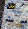
Tried on the breadboard, working !
lcd is fine, but an analog tach still looks better when it comes to funtionality. try revving up and down your engine using lcd and your eyes will have a hard time following the figures. but with analog its easy reading.
I built the led tachometer circuit and worked fine (although the leading zero, when rpm is below 1000, appears as an eight).
My main problem is that I want to use it on my motorcycle, which has a 2-cylinder, four stroke engine with two separate ignition coils.
So, for every two revolutions of the engine, I will pick up one pulse (spark) from any-one of the ignition coils. Is that correct?
Is there a link I can download the original .asm file to try and modify it for my needs?
Any extra help is more than welcome.
Steve, I think there was an error in your display patterns.
I corrected it.
I played around a bit and I encountered a different problem. When using code with common cathode patterns on a common cathode display, multiplexing doesn't work properly and both numbers appear (slightly) on both digits. If I use the common anode patterns code, a 74LS14 inverter and a common cathode display, it works fine!
I even tried changing the multiplexing timing subroutines but nothing happened.
Following is the original code (with the correct display patterns for steve's common anode display led tachometer), can anyone give it a try and tell me if it works? I don't know, maybe it's my display!
This site uses cookies to help personalise content, tailor your experience and to keep you logged in if you register.
By continuing to use this site, you are consenting to our use of cookies.

 hi
hi