Electro Tech is an online community (with over 170,000 members) who enjoy talking about and building electronic circuits, projects and gadgets. To participate you need to register. Registration is free. Click here to register now.
Welcome to our site! Electro Tech is an online community (with over 170,000 members) who enjoy talking about and building electronic circuits, projects and gadgets. To participate you need to register. Registration is free. Click here to register now.
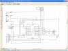
why use the 10k vers the 22k as in the schematic.
and the diode is just to lower the voltage on mclr?? while the resistor lowers the current??
I have several 10k resistors
will insert and progra,m a chip and try the monster out.
oh need to change some code but should work with existing.just need to add a push button to the breadboard
Every one dos it there way The datasheet from pic miro tells you to use a 10 k to pull mclr up to VDD it makes your chip run right. The diode blocks Vdd from getting 12 volts when you program the chip or you would need a jumper for mclr. some chips you can get by with out it and some will drive you crazy trying to find out what you did wrong
So I always use the diode and the resistor like I showed you but a 22k will work I just use a 10k
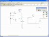
to be connected to pin 6 of the amp, not the transistor. Must of happened when I moved a large block of components over at one time.
THANKS I need to double check things
now onto code
I added everything in red
Device = 18F1320
Clock = 8 // 8MHz clock
Config OSC = INTIO2, WDT = OFF, LVP = OFF
Dim NOT_RBPU As INTCON2.7
Dim TMR1IE As PIE1.0
Dim TMR1IF As PIR1.0
Dim TMR1 As TMR1L.AsWord
Dim Speaker As PORTB.3
Dim SpeakerTris As TRISB.3 DIM amp as PORTA.1 // turns on amp power Dim dip3 AS PORTB.1 //changes delay DIM dip4 AS PORTB.0 //changes # of tones
//global variables
Dim Seed As LongWord, Tone As Byte
Dim i As Byte
//half period delays = clock speed divided by 2*frequency
Const Tones(18) As Word = (2000000/12000,2000000/10000,2000000/8000,2000000/6000,2000000/4000,1000,
2000000/12000,2000000/10000,2000000/8000,2000000/6000,2000000/4000,1000,2000000/12000,2000000/10000,2000000/8000,2000000/6000,2000000/4000,1000)
//interrupt routine
Interrupt MyInt()
T1CON.0=0 //stop timer
TMR1=-Tones(Tone) //reset period
T1CON.0=1 //restart timer
If Tone=5 Then //if silence
Speaker=0 //speaker off If PORTB.1=1 then speed=200 Else speed = 25
Else //otherwise Toggle (amp) // turn on amp
Toggle(Speaker) //make sound
EndIf
TMR1IF=0 //clear interrupt flag
End Interrupt
Function Rand(Range As Byte) As Byte
Dim i As Byte, feed As Bit, temp As Word
For i = 0 To 7 //generate 8 bits
Feed = Seed.30 Xor Seed.27 //make new bit
Seed=Seed*2+Feed //shift seed left and add new bit
Next
Temp=(Seed And 255) * Range //change Rand from 0 to 255
Rand = Temp/256 //to 0 to (Range-1)
End Function
//main code starts here
OSCCON = $72 //select 8MHz internal clock
NOT_RBPU=0 //WPUs on port B
ADCON1=$70 //all digital
T1CON = %10000001 //pre=1
Tone=5 //no sound please
TMR1IE=1 //enable timer 1 interrupt
Enable(MyInt) //set interrupt going
SpeakerTris=0 //Setup Port
Seed=$12345678 //seed random number
While(TRUE) //repeat forever
If PORTB.2=1 Then //if PIR activated portRB2 is high
For i = 1 To 200 //play 20 tones
Tone=Rand(5) //each tone is random frequency
DelayMS(speed) //and for 1.00 seconds
Next //end for loop
Else //otherwise
Tone=5 //silence
i=Rand(255) //make rand more random
EndIf //end if condition
Wend //end of while loop
I moved said mistake
this should work
still contemplating the split cells
A 3 cell AAA holder = .89 cents. need 2 = $1.78
the 6 cell AAA holder is $1.38 + .05 cents for diode.
wonder if the split batteries is worth the extra 40 cents per unit?
earlier someone mentioned using a 2n7000 mosfet instead of the 2n2222 transistor for the amp-its better??
It uses less power then the npn. But takes more parts to use I would use the npn
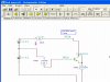
P.S you can get better npn's then the 2n2222 and why did you change the base resistor to 470 ohms thats uses 10.417 Milliamps the 1k used 5Milliamps Oh you don't need split cells holder a 6 cell will work just as good you just solder a wire on three cells of it. **broken link removed**
You don't want to toggle the amp pin, just turn it ON and OFF.
In the interrupt I would do,
Code:
Interrupt MyInt()
    T1CON.0=0               //stop timer
    TMR1=-Tones(Tone)       //reset period
    T1CON.0=1               //restart timer
    If Tone=5 Then          //if silence
        Speaker=0           //speaker off
        amp=0               //turn amp off
    Else                    //otherwise
        amp=1               //turn amp on
        Toggle(Speaker)     //make sound
    EndIf
    TMR1IF=0                //clear interrupt flag
End Interrupt
I would move the reading of the dip switches to within the while loop. You also need to define AmpTris and set it at the same point that SpeakerTris is set.
If you post your code again, try using the [code] and [/code] tags.
looked at the data sheet of the holder and yes it is doable but the end user (the persons with all the deer running rampant eating their yard) needs to (better appearance) have a battery holder that won't become disconnected or break a wire off.
am even considering putting a plug on the battery case so the batteries can be removed much easier.
Yo Pommie - will make changes to code as suggested. I is just a hick with this code stuff - only time with basic was the Commodore computer years.
the 2n2222 is cheap, it will do the job unless you have a better suggestion. Always open for suggestions.
as far as the resistor - I just used Bluerooms suggestion. Ran through Tina Multisim and a website transistor simulator.
need to investigate the
Code:
 in swordfish I assume.
even thought about just zipping the file and posting?
 tags[/b]

not sure I did the code tags right?
moved dip switch read into interrupt section and define amptris(oups I see I didn't capitalize Dim amp

}
[code]
Device = 18F1320
Clock = 8 // 8MHz clock
Config OSC = INTIO2, WDT = OFF, LVP = OFF

Dim NOT_RBPU As INTCON2.7
Dim TMR1IE As PIE1.0
Dim TMR1IF As PIR1.0
Dim TMR1 As TMR1L.AsWord
Dim Speaker As PORTB.3
Dim SpeakerTris As TRISB.3
DIM amp as PORTA.1 // turns on amp power
Dim ampTris As TRISA.1
Dim dip3 AS PORTB.1 //changes delay
DIM dip4 AS PORTB.0 //changes # of tones
//global variables
Dim Seed As LongWord, Tone As Byte
Dim i As Byte

//half period delays = clock speed divided by 2*frequency
Const Tones(18) As Word = (2000000/12000,2000000/10000,2000000/8000,2000000/6000,2000000/4000,1000,
2000000/12000,2000000/10000,2000000/8000,2000000/6000,2000000/4000,1000,2000000/12000,2000000/10000,2000000/8000,2000000/6000,2000000/4000,1000)

//interrupt routine
Interrupt MyInt()
T1CON.0=0 //stop timer
TMR1=-Tones(Tone) //reset period
T1CON.0=1 //restart timer
If Tone=5 Then //if silence
Speaker=0 //speaker off
amp=0 // amp off
Else //otherwise
Toggle(Speaker) //make sound
EndIf
TMR1IF=0 //clear interrupt flag
End Interrupt
Function Rand(Range As Byte) As Byte
Dim i As Byte, feed As Bit, temp As Word
For i = 0 To 7 //generate 8 bits
Feed = Seed.30 Xor Seed.27 //make new bit
Seed=Seed*2+Feed //shift seed left and add new bit
Next
Temp=(Seed And 255) * Range //change Rand from 0 to 255
Rand = Temp/256 //to 0 to (Range-1)
End Function

//main code starts here

OSCCON = $72 //select 8MHz internal clock
NOT_RBPU=0 //WPUs on port B
ADCON1=$70 //all digital
T1CON = %10000001 //pre=1
Tone=5 //no sound please
TMR1IE=1 //enable timer 1 interrupt
Enable(MyInt) //set interrupt going
SpeakerTris=0 //Setup Port
Seed=$12345678 //seed random number
While(TRUE) //repeat forever
If PORTB.2=1 Then //if PIR activated portRB2 is high
If PORTB.1=1 then speed=200
Else speed = 25
For i = 1 To 200 //play 20 tones
Tone=Rand(5) //each tone is random frequency
DelayMS(speed) //and for 1.00 seconds
Next //end for loop
Else //otherwise
Tone=5 //silence
i=Rand(255) //make rand more random
EndIf //end if condition
Wend //end of while loop
using the 470 ohm base resistor= 7.79 ma
the 1K shows 3.72ma
I assume that to verify saturation I do 2 simulations
one with the collector shorted to emitter and one without the short
if both show similar results then the transistor must be saturated??
from 3 ma min - 8 ma max
I didn't even think about actually powering the amp off the PIC if it is even doable??
the 2n2222 is maybe overkill or just a way to isolate from outside world??
This PIC thing is all new
This site uses cookies to help personalise content, tailor your experience and to keep you logged in if you register.
By continuing to use this site, you are consenting to our use of cookies.