Electro Tech is an online community (with over 170,000 members) who enjoy talking about and building electronic circuits, projects and gadgets. To participate you need to register. Registration is free. Click here to register now.
Welcome to our site! Electro Tech is an online community (with over 170,000 members) who enjoy talking about and building electronic circuits, projects and gadgets. To participate you need to register. Registration is free. Click here to register now.
OPTION 1-program what is in Junebug then remove, insert into bread board
OPTION 2 - finish cutting the 40 pin IDC (hard drive cable) then solder pins on cable to insert into bread board
OPTION 3 - solder a 18 pin socket to perfboard, solder the altered 40 pin hard drive cable to perfboard. Then program chip . Remove from perfboard and insert onto bread board
Oh yea the PIR output 3v for about 1 second then waits for another movement.
I need to investigate the jumper on the PIR.
egads to many decisions!!
Now you got me really thinking
If I connect the LM386 Vdd+ pin #6 to a transistor then control the transistor with say RB4 or ??. Something that will turn off the base of the transistor thus shutting down the LM386
When the PIR triggers (wakes up the PIC) it then turns on the transistor thus turning on the LM386
The LM386 has an input load resistance of 50K which the PIC seems to handle but the 3ma current draw the batteries won't last as long as if the LM386 was OFF completely
Then need to configure this sleep routine. In the code I recall seeing sleep. is this the same as what blueroom is talking about?
controlling the amplifier using an NPN transistor controled by the PIC
probably nothing new?
should the VDD pin 6 of the LM386 be on the collector or emitter?
then we will discuss code to put little PICy to sleep.
9 / .003 = 3000 /10 = 300 ohm. I guess a 470 to be safe?
audioguru mentioned that for most cases the base resistor is 1/10th the load resistance
I just got used to using PNP for sourcing and NPN for sinking current. The current flows in the direction of the arrow so it's correct in your drawing.
Also if you want it to sleep put the PIR sensor on a pin that can wake it up, look for pins in the datasheet that have an INTx input. INT0, INT1 & INT2 all exist on the 18F1320. These can all wake up the PIC from sleep.
A sleeping PIC draws almost nothing, I would run it from 4AA batteries and dont use a regulator. 6V is on the high side and slighty out of spec (original PICs were good to 7V) but if you want to play it safe a 1N4148 in front of VDD will drop the voltage and last much much longer than a power wasting linear regulator and a 9V battery.
at first knowing the reg will draw current as well
on the batteries = I contemplated using AA batteries but the AAA batteries fit real nice inside the 1 1/4 pvc weatherhaed. and its cheaper-only $5 vers $8 for an enclosure made for this type of app.
got a board design pretty much done. just need to remove regeulator, add base resistor and connect PIR to a different pin (removing the #3 dip switch and connecting the PIR to RB2/INT2
have to add some code??
I'd add a simple 5 pin programming plug (any 1x5 0.1" header) you don't need the 6th (LVP) pin. **broken link removed**
If you're curious about the above device I just found it when Googling.
Here's the complete link. http://www.kwantlen.ca/science/physics/faculty/dpeirce/notes/timer_box/
got sidetracked w/ dinner and hav't got back to it.
only using 5 pins. cut from a 40 pin hard drive cable.
need to put header pins on my list at Mouser.
took out the reg, 2 caps, added a 1n4148, changed the PIR connection.
boy this board is small
wish I had gotten into this long time ago.
??? What software did you use for your boards? they are nice and neat.
doing a DIY etch using the Pulsar method
traces are all .25mm
Again thanks for all your help as well as Pommiee and be80be
I need to head to bed and hopfully the CRITTER RIDDER will work tomorrow.
any special code for the sleep as well as the INT routine for the PIR
Your PNP solution won't work. If you drive the base with 5V then the emitter will be at 4.7V. You could use a NPN on the gnd side to do the same thing and that will work but something like a 2N7000 mosfet will produce a better result.
I also don't understand why you are messing about with IDC cables. Why not just buy the right parts and know you have something that works rather than something dodgy?
I don't get why you you'd use a 10 pin idc cable when all you need is 5. And the junebug is basicly a pickit2 with experimenter board. I would make one adapter from 10 pin IDC to the 6 pin female that way
you could use all the boards that you can get for the pickit2. And you would only need a 5 pin male header on your board. This show you only thing is you'll have a IDC to 6 pin cable and I can plug my pickit strait in to my board **broken link removed**
The round board adds the leds and buttons that are on a junebug Thats how i tried some of the code I posted for the junebug.
I used the 2x5 as you can't get ribbon cable crimp connector for a 1x5, you have to solder. It also makes it easy to use with a breadboard. **broken link removed**
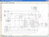
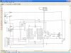
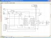
and adding the 1n4148 diode for the power supply.see schematic I posted.
Next step is to assemble a perf board as be80be has w/ 18 pin socket, a 5 pin header. Wire up a plug on perf board so I can access the pins on the PIC to connect to a breadboard (same as be80be has in picture.)
I guess GREAT minds think alike --LOL
and for how long ??
need to add code to put little PICy to sleep and PIR int routine then the dip switch needs to be coded.
one to change delay variable and other to change number of tones (resistor network in PIC?)
putting the NPN on the grd side
you mentioned a mosfet 2n7000
never worked w/ mosfets
schematic
and how or why would it be better?
reason for the ICD cables is to be able to progran IN CIRCUIT
hey are just tempory, not used except to program
first I found a mistake in my schematic R3 instead of 10K it is supposed to be 22K (looked and followed the Junebug schematic.Have to wait until Monday for another 22K, used last one in my ICD programming board (for testing on breadboard)
To program a PIC on a separate board do I turn off the first 3 dip switches only or ??
This site uses cookies to help personalise content, tailor your experience and to keep you logged in if you register.
By continuing to use this site, you are consenting to our use of cookies.

") so it's correct in your drawing.
so it's correct in your drawing.