Electro Tech is an online community (with over 170,000 members) who enjoy talking about and building electronic circuits, projects and gadgets. To participate you need to register. Registration is free. Click here to register now.
Welcome to our site! Electro Tech is an online community (with over 170,000 members) who enjoy talking about and building electronic circuits, projects and gadgets. To participate you need to register. Registration is free. Click here to register now.
It could easily be a driver fault; if the drive voltage is not high enough, the power transistors will only partly turn on and dissipate far too much power..
It could easily be a driver fault; if the drive voltage is not high enough, the power transistors will only partly turn on and dissipate far too much power..
You need an oscilloscope & connect capacitors with similar values to the power device gate-source ratings in place of them, plus isolating the main rectifier so there is no high voltage supply on the power transistor terminals.
You need an oscilloscope & connect capacitors with similar values to the power device gate-source ratings in place of them, plus isolating the main rectifier so there is no high voltage supply on the power transistor terminals.
Are the drive transformer windings all OK?
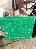
And can you compare the components in the two gate circuits against each other to see if any resistors are open circuit, or the diode faulty.
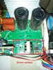
With a single transformer I do not see how it can have drive to one side and not the other, unless something has failed in that area.
Are the drive transformer windings all OK?
And can you compare the components in the two gate circuits against each other to see if any resistors are open circuit, or the diode faulty.
With a single transformer I do not see how it can have drive to one side and not the other, unless something has failed in that area.
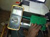
The gate voltage should be a string of pulses, not a fixed DC voltage. As such, the only reliable way to see what is there is with a scope.
Your voltmeter will give an approximation of the average pulse amplitude.
[/QUOTE
yes, the voltage does not stable ,
what's the normal voltage to feed to the gate , even if I don't have a scope to the frequency ?
Are the drive transformer windings all OK?
And can you compare the components in the two gate circuits against each other to see if any resistors are open circuit, or the diode faulty.
With a single transformer I do not see how it can have drive to one side and not the other, unless something has failed in that area.
The controller will vary the duty cycle of the pulses to control the output of the welder. The average voltage will be the peak voltage * the duty cycle.
From the datasheet for the FGH50T65UPD, the maximum voltage is 20 volts (the peak voltage of the pulse). Anything higher than that can kill the part.
This site uses cookies to help personalise content, tailor your experience and to keep you logged in if you register.
By continuing to use this site, you are consenting to our use of cookies.