Continue to Site

Welcome to our site!

Electro Tech is an online community (with over 170,000 members) who enjoy talking about and building electronic circuits, projects and gadgets. To participate you need to register. Registration is free. Click here to register now.

  • Welcome to our site! Electro Tech is an online community (with over 170,000 members) who enjoy talking about and building electronic circuits, projects and gadgets. To participate you need to register. Registration is free. Click here to register now.

I need a tip. It about LEDs and V.REGs

Status
Not open for further replies.

brodin

New Member
I have a question about this led cluster, which I have bought:
**broken link removed**

I am going to use this on my motorcycle as a shiftlight. I have done the circuit, which is working good. I am just going to attach a better light source than a simple LED.

The datasheet says "FORWARD VOLTAGE = 10.8V " for the 6 red LEDs. As I am going to use the battery on the bike to drive the LEDs i have about 13.5 V.
Is also says "STEADY CURRENT = 30 mA".

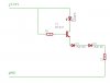
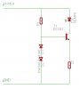
Is the correct calculation like this then:?
R = ( Ubattery - 10.8 ) / 30E-3

I suppose the battery voltage will not always be 13.5V, so wouldn't it be best to have a voltage regulator here? But will it work to use a standard 7812 vreg, or do i need more than 1.5V over 12V. I mean if the batteryvoltage is 12.5V I guess the output of a 7812 is not 12V but less.

Am i right about this, and what suggestion can you give me to get a constant voltage?
 
There are several options.
(1) Yu can use a reg, but not a standard 7812. The 7812 needs at least 2v of "dropout voltage". At 12.6v it will only put out 10.6v. You would need to find a "low dropout" version, some are down to like 0.5v or so.

(2) Size the resistors for the max voltage. If your system can go up to 14.6v, you can use that; R=(14.6-10.8/0.030).

(3) Note that with (2) 12.8v your system is only half the intensity as it is at 14.8v; it is not very stable. The effect of a 2v variation will be less dramatic if you use fewer LEDs in series so you have less of your voltage in fixed "forward voltage" and drop more voltage across the resistor.
 
The problem is that i can not use fewer LEDs in series because this is a LED module, so i can't change the circuit.

I suppose i have to find a low dropout v.reg then. Any tips?


I thought of another solution. Maybe i could use a PIC with a PWM module instead of the 12F629, which I am using now. Then I could control the current by using PulseWidthModulation. The leds allow a peak current of 150mA so it might be possible.
But how do i figure out the current? Meassuring the voltage over the known resistor with the A/D module in the PIC?

What do you guys think about that?
 
brodin said:
The problem is that i can not use fewer LEDs in series because this is a LED module, so i can't change the circuit.

Instead of a resistor, feed the LED chain from a constant current source, this will help to keep the current constant as the supply changes. As with any circuit, it will require some amount of extra voltage to work, but less than a voltage regulator.
 
brodin said:
What kind of component do you mean? Can you please give me an example.

Something like this!.
 

Attachments

  • constant_current_124.gif
    constant_current_124.gif
    2.2 KB · Views: 1,438
Thanks a lot Goodwin for the scematics. I am not good in analog electronics, so if someone could tell me what kind of diodes to use i would be glad. As for the transistor, will it work with a BC547?

If someone feel for it, please give me a short description of how a circuit like this works.
 
brodin said:
Thanks a lot Goodwin for the scematics. I am not good in analog electronics, so if someone could tell me what kind of diodes to use i would be glad. As for the transistor, will it work with a BC547?

It's a PNP transistor, a BC557 should be OK, any silicon diodes will do, IN4148 are a standard small signal silicon diode which I often use, they would be fine.

If you wanted to use a BC547 you could invert the entire circuit, and have the transistor in the negative leg of the LED's.

If someone feel for it, please give me a short description of how a circuit like this works.

It's very simple, the two silicon diodes drop around 1.4V across them, and this will be fairly constant. So this fixes the base voltage at 1.4V less than the positive rail. The transistor drops 0.7V between base and emitter, so the emitter is 0.7V less than the positive rail - again this voltage will be fairly constant.

This means the emitter resistor (which is a constant value) has a constant voltage across it, which means (by simple ohms law) it MUST have a constant current through it. Because of the way a transistor works, most of this current will be provided from the collector current of the transistor (with a very small amount from the base current), so the current through the collector will be constant as well.

As the only place the collector can provide this current from is through the load, the load current will remain constant as well.

It's not a 'great' circuit, but it's simple and cheap - and will work a LOT better than a resistor.

To alter the current simply change the value of the emitter resistor, lower is more current, higher is less current.
 
Sebi said:
Or simply put a red LED to this position.

Yes, an LED is often used as a voltage reference, but how does the voltage drop compare to two silicon diodes?, in this case it's important to try and keep voltage losses as low as possible.
 
This circuit works fine, though I don't really understand the thing about R1 at 1K. What task does that resistor have in this circuit?

I could use this for a same kind of "led series", but with a forward voltage of 8.8 V, right?
 
brodin said:
This circuit works fine, though I don't really understand the thing about R1 at 1K. What task does that resistor have in this circuit?

It provides the required current through the two diodes, and also provides the base current for the transistor - without it there it wouldn't work at all.

I could use this for a same kind of "led series", but with a forward voltage of 8.8 V, right?

Yes, the circuit will keep the current 'constant' for one LED or above - until you run out of voltage!, probably at around 10V-11V of LED's.
 
brodin said:
How would the scematic look like if i used a NPN BC547 transistor?

Just mirror the entire circuit (vertically), so the emitter resistor and two diodes connect to the negative rail instead of the positive - bear in mind the two diodes must still be connected the correct way round!.
 
I have tried to make a circuit with a BC547. But I suppose something is missing here, or maybe everything is wrong. Please help me to finnsih the scematic to get the same function as in the scematic above with a PNP transistor.
 

Attachments

  • led_699.jpg
    led_699.jpg
    32.3 KB · Views: 366
brodin said:
I have tried to make a circuit with a BC547. But I suppose something is missing here, or maybe everything is wrong. Please help me to finnsih the scematic to get the same function as in the scematic above with a PNP transistor.

It's wired totally different to the previous circuit I posted!.

The 22 ohm should go from the emitter to 0V, and the two diodes from base to 0V - just a mirrored image of the previous version.
 
Ah, now I get it, it's that simple. Thanks for explaining for me!
 

Attachments

  • led_182.jpg
    led_182.jpg
    37.2 KB · Views: 350
Status
Not open for further replies.

Latest threads

New Articles From Microcontroller Tips

Back
Top