Electro Tech is an online community (with over 170,000 members) who enjoy talking about and building electronic circuits, projects and gadgets. To participate you need to register. Registration is free. Click here to register now.
Welcome to our site! Electro Tech is an online community (with over 170,000 members) who enjoy talking about and building electronic circuits, projects and gadgets. To participate you need to register. Registration is free. Click here to register now.
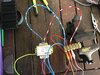
I have marked. The blue wirer with yellow rings. Same side as the red, white wirer with rings.
i joined the blue , yellow ring wires to red ,white wirer.
Then joined the blue wirer together with the red and there was a spark so I disconnected red and blue.What do you suggest. Sorry about being a pain. Could you give me a circuit Digram. Of what you want.
thank you Greg.
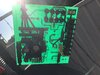
I have achieved 18 Volta as you can see by the photos.
Where do I go from here Can I wirer it onto the board.
Blue connected to the red white
red, Blue yellow connected to multi meter
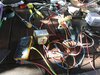
I have connected every thing up .The capacitor. Reading is 12.7 volts DC.
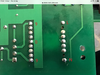
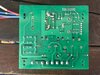
On the opposite side where I have solder the wires is the any thing to be don there As this is where the primary winding for the old transformer was
on the photo of the board you have L and N marked is this where Live 240 v and neutral is connected from Mains Supply
What is the reading on the other capacitor? That should be about -12 V.
You don't have to do anything where the old transformer live and neutral were connected. I don't know how you are supplying the new mains transformer, and you could take wires from where it says L and N on the picture, but you could just have a separate supply.
I just edited my earlier reply, and I hadn't seen your new question.
The relays get 240 V from the screw terminals on the circuit board. You still need that supply to get the motor to work. The transformer runs the electronics, which controls the relays, so that is needed as well.
i removed the relays as they are faulty
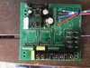
I will supply a photo of the board can you explain to me how I get the relays to switch to enable the motor to run.
It was a 3 phase but I am changing it to 240 v thank you
In the case of a motor that can be connected star for 380 - 420 V and delta for 200 - 240 V, the first thing to do is to connect for the correct voltage.
Then connect the power between two of the phases of the motor, and then the capacitor connects to the other phase. The other end of the capacitor is connected to one of the power wires.
The start torque will be very low compared to running the motor from three phase. The efficiency and maximum power will be somewhat less than compared with running from three phase.
Using a capacitor with a three phase motor to run from single phase has been used on commercial products.
Good Morning from AU
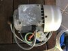
I have the 3 phase motor connected with 240 v Ac and running in the correct direction .There are 2 capacitors connected to the motor . The caps are 7;uf and 8 uf . The start torque and running torque are good .
what I need to know is how do I get the motor to start up when connecting to the board.and pushing start
I have ordered 3 new relays for the board.
This site uses cookies to help personalise content, tailor your experience and to keep you logged in if you register.
By continuing to use this site, you are consenting to our use of cookies.