Continue to Site

Welcome to our site!

Electro Tech is an online community (with over 170,000 members) who enjoy talking about and building electronic circuits, projects and gadgets. To participate you need to register. Registration is free. Click here to register now.

  • Welcome to our site! Electro Tech is an online community (with over 170,000 members) who enjoy talking about and building electronic circuits, projects and gadgets. To participate you need to register. Registration is free. Click here to register now.

How does a transistor amplify current or voltage?

Status
Not open for further replies.
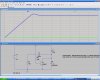
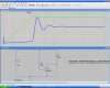
I think it would because with no feedback if the resistor is of a low enough value the transistor will come out of sat. So it may depend on the value of the resistor.

I think it would just never achieve sat. Once the transistor saturates, collector current would be constant, not increasing ( no feedback ) Depending on the value of the reisitor, the transistor either saturates or it doesn't, IMHO.
 
MrAl,

You have to realize though that you can not make a statement like that when you talk about saturation, ie collector current 'only'. Yes, 100ma is within the 'range of saturation' but then so is 10ma, and 1ma, but without the proper drive we still cant obtain (nor maintain) saturation.
In other words, we have to specify collector current and also base current to tell if the device is in sat.
Example:
100ma collector current and 10ma base current, transistor is (most likely) in saturation.
100ma collector current and 1ma base current, transistor might be in sat.
100ma collector current and 100ua base current, transistor probably is not in sat.
100ma collector current and 10ua base current, transistor is most definitely not in sat.
100ma collector current and 0.00 base current, transistor is not in sat.
So it's a matter of BOTH Ic and Ib, not just Ic.

You are making my point for me by listing all those currents. Neither Ic or Ib determine saturation or not. When Vcb is zero or less, and the transistor loses its reverse bias, it will go into saturation. Ib and Ic don't affect saturation unless they pull down the reverse bias. Do a differential voltage measurement between the base and collector. You will find its zero point syncs perfectly with whether the transistor is saturated or not.

I think what Jony was saying is that for an ideal coil (as in simulation) the coil can support any voltage you throw at it so there's no reason for that coil to force a zero voltage (across it) condition. Also, you have to keep in mind that even without that feedback circuit (Q1) the transistor comes out of sat, and that's with no feedback whatsoever.

Why are we talking about ideal coils? The coil has resistance, as does the voltage source and the transistor. That establishes a current limit. The coil's back voltage eventually becomes close to zero as it approaches its current limit.

By disconnecting the capacitor, I see that the transistor operates permanently in the active region with no excursions into saturation. I surmise that on startup, the capacitor momentarily sends Q2 into saturation by making its collector the same voltage as the base of Q1 (0.7 volts). Then it latches and stays in saturation until the back voltage across the coil decreases.

Ratch
 
OK for this circuit
**broken link removed**

We assume that at time 0 Q1 and Q2 are full "ON".
The base current is equal
Ib_Q2 = (3V - 0.2V - 0.7V)/3.5K ≈ 600uA
And for sure Ib_Q2 remains constant (600uA).
At time 0 Ic_Q2 = 0A because almost all voltage is across L1.
The current in the inductor start ramps up in I =3V*t/100uH = 30mA/µs
And form datsheet I get this DC output characteristics
**broken link removed**
An form LTspice for 2N4401
**broken link removed**
During the phase when a coil current ramps up (30mA per microsecond ) the operation point of a Q2 moves up the curve from point 1 to 2.
And when Ic_Q2 reaches the point 2 Q2 will start to come out of saturation.
So we need at least 120mA inductor current (and this will take 4µs) to Q2 come out from sat. And this will initiate the whole positive feedback stuff, which in the end cut-off all BJT.
**broken link removed**
So the primary cause for all BJT start to cut-off is Q2 that leaves saturation region and enter into active region.
 

Attachments

  • gen3.asc
    1.8 KB · Views: 206
Last edited:
Jony130,

We assume that at time 0 Q1 and Q2 are full "ON".

If you don't mark the box "Start external DC supply voltages at 0 volts" in the Edit Simulation Dialog box, Q2 will go into the active region and stay there. So if the circuit starts with Q1 & Q2 ON, it will not self-start its oscillation. Try it and see.

And when Ic_Q2 reaches the point 2 Q2 will start to come out of saturation.

Q2 will come out of saturation when its c-b reverse bias is restored regardless of what Ic is. Look at the simulation, and do a differential voltage trace between the base and collector. Its zero point of the differential voltage tracks exactly with the saturation state.

So the primary cause for all BJT start to cut-off is Q2 that leaves saturation region and enter into active region.

Q2 is always either in the cutoff or saturation region. It is never in the active region except when it is transitioning. Look at Ic of Q2 in the simulation and see.

Ratch
 
MrAl,


You are making my point for me by listing all those currents. Neither Ic or Ib determine saturation or not. When Vcb is zero or less, and the transistor loses its reverse bias, it will go into saturation. Ib and Ic don't affect saturation unless they pull down the reverse bias. Do a differential voltage measurement between the base and collector. You will find its zero point syncs perfectly with whether the transistor is saturated or not.


Why are we talking about ideal coils? The coil has resistance, as does the voltage source and the transistor. That establishes a current limit. The coil's back voltage eventually becomes close to zero as it approaches its current limit.

By disconnecting the capacitor, I see that the transistor operates permanently in the active region with no excursions into saturation. I surmise that on startup, the capacitor momentarily sends Q2 into saturation by making its collector the same voltage as the base of Q1 (0.7 volts). Then it latches and stays in saturation until the back voltage across the coil decreases.

Ratch


Brownout:
Sorry, i meant that happens with a resistor given that we increase the voltage as in one of the experiments i posted.
Check it out that way and see what you think.

Ratchit:
Yeah, dont try to turn it around to make your own point.
You keep saying Vcb and i already agreed with you, but it takes Ic to get to Vcb that you talk about. You just dont see it and you never will.

We talk about ideal coils when the resistance in the coil is low enough to be considered with no resistance. The theory goes with either some resistance or no resistance and you are the only one saying now you dont want to work with zero resistance. Look at it this way, 1.4 ohms would draw 3/1.4 amps at 3 volts which is at least 2 amps. The transistor wont allow that, and it is not the inductor series resistance that limits the current! If you think so, lower the resistance more then to 0.01 ohms. That's 3/0.01 amps, which the cells would not be able to supply, yet their minuscule series resistance (0.2 ohms) wont limit it either: 3/0.2 is 15 amps. That's not limiting.
The coils voltage does not really have to go to zero it just has to conduct more current, and 2 amps is pretty high already, yet it never gets there. Why? If that was the current limit then the transistor would see 2 amps, yet it doesnt. Why?

By disconnecting and operating as you say, you are working with a different setup then. You have to stick to what the transistor actually gets no matter what circuit you use. By using the correct circuit(s) you will see the transistor behave no matter what circuit you choose. By chosing the wrong circuit or different operation, you wont see it happen the same way. The circuit has to start from low current as the real circuit does if you are to use a different circuit, not from full supply voltage.

You just wont see this no matter what anyone says because you are only looking for ways to proved whatever it is you want to try to prove, which im not even sure what that is.
I already agreed with you about Vcb yet you keep bringing that up again. Without Ic Vcb can never rise. Try it, try to get Vcb to rise without increasing Ic at the point of operation where it matters.
Also, run the osc circuit as it should run and look at the collector current and bias on the base of Q2. The collector current increases, it's Vce rises, the transistor comes out of sat, and that means Vce rises more, fed back through the cap Q1 turns off, that turns off Q2. Look at the simulation you run and look at the one i posted. It's pretty clear.

Look at Jony's post! That plot shows Vce vs Ice. Now try to get out of that one :)
If you increase Ice (as the graph y axis) you see the sat voltage rise and then break out of sat at the knee(s).
Try to argue against that one.
This is exactly what i had been talking about here, and this shows how the circuit forces the transistor out of sat.
Like i said, if you want to 'detect' Q2 coming out of sat with a measurement of Vcb, that's fine with me, but it will take increaseing Ice as in that plot to get it there. You're going to have to acknowledge this sooner or later.

Since you dont want to acknowledge anything anybody else has to say about this, we'll have to start listing this discussion point by point, and since you are arguing against we'll list them by your points and see what we get.

Your Point 1:
The series resistance of the coil limits the current.
Counter point proven:
No it doesnt, because its resistance is too low, 1.4 ohms, which is 2 amps and the transistor never gets there.

Your Point 2:
The series resistance of the batteries limits the current.
Counter point proven:
No it doesnt, because their resistance is too low, 0.2 ohms, and that would be 15 amps and the transistor never gets there.

Your Point 3:
The series resistance of the cells AND the coil limits the current.
Counter point proven:
No they dont, because their resistance together is 1.6 ohms, which is roughly still close to 2 amps and the transistor never gets there.

Your point 4:
The Vcb is an indicator of the saturation state of the transistor.
Counter point:
None, agreed.

Your point 5:
The Vcb takes the transistor out of saturation itself.
Counter point:
Not really, but partially agreed because it's too hard to prove otherwise, but in any case Vcb can only get to the required value by an increase in current Ice.

Your point 6:
It's Vcb that takes the transistor out of saturation itself, not Ice.
Counter point:
You can not EVER reach Vcb required unless you increase Ice.

Your point 7:
You dont have to increase Ice because of the feedback which cuts off Q1 and hence Q2.
Counter point:
Q2 comes out of saturation before the feedback arrives at Q1, as proven by simulation. In fact, if you look closely at the simulation you can see the transistor behaving exactly as Jony's plot of Ice vs Vce indicates it should. You can see the Vce start to rise BEFORE the feedback arrives at Q1.

Your point 8:
You dont agree with Jony's plot of Vce vs Ice.
Counter point:
It's a simple two dimensional plot that the manufacturer supplies to show typical operation of the transistor.

Your point 9:
The transistor region of saturation includes Ic of 100ma and even higher, so the transistor would stay in saturation.
Counter point:
You can not conclude that the transistor stays in sat unless you know Ib also, and given that Q1 is fully turned on, Ib will be constant and will not change until the feedback arrives. The transistor operates at constant Ib and it's only Ic that changes.

Your point 10:
The general operation of the osc circuit is that something other than Ic causes the rise in collector voltage and therefore the rise in Vcb.
Counter point PROVEN:
It is actually Ic that causes the rise in Vce which causes the rise in Vcb. To prove this, we only have to look at the simulation and take it one microsecond at a time. The simulation clearly shows that the transistor Vce starts to rise BEFORE the feedback gets high enough to cut off Q1. To make this more clear, we can use another circuit that has no feedback, or even simply short out Q1 collector to emitter to keep Q2 turned on constantly. What we see is as we turn the circuit on is that the collector current rises as the inductor allows with time, and it continues to rise until the transistor starts to come out of saturation. Lo and Behold, the transistor comes out of saturation even with no feedback...what a surprise :)
 
Last edited:
Q2 will come out of saturation when its c-b reverse bias is restored regardless of what Ic is.

The simulation clearly shows Q2 coming out of saturation when IC=120mA.

Q2 is always either in the cutoff or saturation region.

That's incorrect, as the simulation clearly shows. Q2 leaving the saturation region is the only thing that stops the current from rising past 120mA. A saturated bjt can't do it. No matter how much you distort the basic laws of circuit voltage, current and resistance, they prove you wrong each time you make such a mis-statement.
 
Hello again,


Here are two simulation runs for the Brinkmann circuit.

Fig 1 shows Q1 cutting off, but only after Vce starts to rise. The point where Q1 starts to cut off is after Vce rose about 0.6v, which means it's hard to tell what happens first (however it did actually rise not stay the same), so in Fig 2 the capacitor was decreased to 380pf and now we can see that Q1 does NOT start to cut off until Vce rises to nearly 1v (0.99v).
Now in the Fig 1 we might be able to argue that Vce only had to rise a little, so it 'might not' have come out of sat yet because Vce only equals 0.6v and so the feedback couples that to Q1 base. But, in Fig 2, Vce rises clearly to 0.99v before any action occurs in Q1, and so if we argue that in Fig 1 the transistor came out of sat at 0.6v due to the feedback then we can not also argue that the transistor came out of sat at a different voltage (0.39 volts higher than 0.6v) too because the base drive is the same in both cases (Q1 is conducting).

Thus, at the very least in Fig 2 the transistor Q2 comes out of saturation due to some reason other than the feedback and i dont see any way around this, and the only reason left is Ic increasing.
 

Attachments

  • BrinkmannAnalysis-01.gif
    BrinkmannAnalysis-01.gif
    16.6 KB · Views: 242
Last edited:
MrAl,

Yeah, dont try to turn it around to make your own point.
You keep saying Vcb and i already agreed with you, but it takes Ic to get to Vcb that you talk about. You just dont see it and you never will.

Turn what around? OK, so we agree that the reverse bias voltage brings the transistor out of saturation and that Vcb can be changed by a change of collector voltage or base voltage. Current changes usually come with voltage changes.

We talk about ideal coils when the resistance in the coil is low enough to be considered with no resistance. The theory goes with either some resistance or no resistance and you are the only one saying now you dont want to work with zero resistance. Look at it this way, 1.4 ohms would draw 3/1.4 amps at 3 volts which is at least 2 amps. The transistor wont allow that, and it is not the inductor series resistance that limits the current! If you think so, lower the resistance more then to 0.01 ohms. That's 3/0.01 amps, which the cells would not be able to supply, yet their minuscule series resistance (0.2 ohms) wont limit it either: 3/0.2 is 15 amps. That's not limiting.
The coils voltage does not really have to go to zero it just has to conduct more current, and 2 amps is pretty high already, yet it never gets there. Why? If that was the current limit then the transistor would see 2 amps, yet it doesnt. Why?

I removed the coil and voltage source resistance, and the circuit still runs fine. I surmise that the transistor comes out of saturation before those high currents are reached.

By disconnecting and operating as you say, you are working with a different setup then. You have to stick to what the transistor actually gets no matter what circuit you use. By using the correct circuit(s) you will see the transistor behave no matter what circuit you choose. By chosing the wrong circuit or different operation, you wont see it happen the same way. The circuit has to start from low current as the real circuit does if you are to use a different circuit, not from full supply voltage.

I disconnected the capacitor because you said in post #357 that the transistor will come out of saturation without feedback. It never goes into saturation without the capacitor, but instead operates steadily in the active region.

You just wont see this no matter what anyone says because you are only looking for ways to proved whatever it is you want to try to prove, which im not even sure what that is.
I already agreed with you about Vcb yet you keep bringing that up again. Without Ic Vcb can never rise. Try it, try to get Vcb to rise without increasing Ic at the point of operation where it matters.
Also, run the osc circuit as it should run and look at the collector current and bias on the base of Q2. The collector current increases, it's Vce rises, the transistor comes out of sat, and that means Vce rises more, fed back through the cap Q1 turns off, that turns off Q2. Look at the simulation you run and look at the one i posted. It's pretty clear.

I don't think we are too far apart on this. I assume we are discussing Vce while in saturation. The way I see it, increasing Ic to 130ma does increase the collector about 0.05 volts in this circuit. That in itself will not bring it out of saturation, as shown in the chart where it still can be in saturation at 500 ma. But the positive pulse the coupled to the base of Q1 might be enough to turn off both transistors.

Look at Jony's post! That plot shows Vce vs Ice. Now try to get out of that one :)
If you increase Ice (as the graph y axis) you see the sat voltage rise and then break out of sat at the knee(s).
Try to argue against that one.
This is exactly what i had been talking about here, and this shows how the circuit forces the transistor out of sat.
Like i said, if you want to 'detect' Q2 coming out of sat with a measurement of Vcb, that's fine with me, but it will take increaseing Ice as in that plot to get it there. You're going to have to acknowledge this sooner or later.

He posted so many. Which one are you referring to? Yes, as I said in the previous paragraph, the slight increase of Vce will not bring it out of saturation by itself. It still needs the feedback to help it.

Your Point 1:
The series resistance of the coil limits the current.
Counter point proven:
No it doesnt, because its resistance is too low, 1.4 ohms, which is 2 amps and the transistor never gets there.

It does limit the current, not not enough to matter. The circuit runs fine with both the voltage source and coil set to zero resistance.

Your Point 2:
The series resistance of the batteries limits the current.
Counter point proven:
No it doesnt, because their resistance is too low, 0.2 ohms, and that would be 15 amps and the transistor never gets there.

Agreed.

Your Point 3:
The series resistance of the cells AND the coil limits the current.
Counter point proven:
No they dont, because their resistance together is 1.6 ohms, which is roughly still close to 2 amps and the transistor never gets there.

Same answer as point 1.

Your point 4:
The Vcb is an indicator of the saturation state of the transistor.
Counter point:
None, agreed.

Agreed.

Your point 5:
The Vcb takes the transistor out of saturation itself.
Counter point:
Not really, but partially agreed because it's too hard to prove otherwise, but in any case Vcb can only get to the required value by an increase in current Ice.

Vcb is the definition of saturation. Do whatever you have to do to make Vcb happen.

Your point 6:
It's Vcb that takes the transistor out of saturation itself, not Ice.
Counter point:
You can not EVER reach Vcb required unless you increase Ice.

I believe in this circuit, increasing Ice does not by itself bring the transistor out of saturation. According to the chart, the current can go up to 500 ma and still be in saturation. It needs help from the feedback circuit.

Your point 7:
You dont have to increase Ice because of the feedback which cuts off Q1 and hence Q2.
Counter point:
Q2 comes out of saturation before the feedback arrives at Q1, as proven by simulation. In fact, if you look closely at the simulation you can see the transistor behaving exactly as Jony's plot of Ice vs Vce indicates it should. You can see the Vce start to rise BEFORE the feedback arrives at Q1.

Yes, it would rise before feedback. I believe that the rise in saturation voltage, as small as it is, is coupled to the Q1 feedback. Otherwise, it would not be enough to bring it out of saturation by itself.

Your point 8:
You dont agree with Jony's plot of Vce vs Ice.
Counter point:
It's a simple two dimensional plot that the manufacturer supplies to show typical operation of the transistor.

Are you referring to the Fairchild data sheet? That is where I obtained the 0.05 voltage rise.

Your point 9:
The transistor region of saturation includes Ic of 100ma and even higher, so the transistor would stay in saturation.
Counter point:
You can not conclude that the transistor stays in sat unless you know Ib also, and given that Q1 is fully turned on, Ib will be constant and will not change until the feedback arrives. The transistor operates at constant Ib and it's only Ic that changes.

According to the simulation, Vb of Q1 receives a positive pulse that turns it off when Vce of Q1 rises.

point 10:
The general operation of the osc circuit is that something other than Ic causes the rise in collector voltage and therefore the rise in Vcb.
Counter point PROVEN:
It is actually Ic that causes the rise in Vce which causes the rise in Vcb. To prove this, we only have to look at the simulation and take it one microsecond at a time. The simulation clearly shows that the transistor Vce starts to rise BEFORE the feedback gets high enough to cut off Q1. To make this more clear, we can use another circuit that has no feedback, or even simply short out Q1 collector to emitter to keep Q2 turned on constantly. What we see is as we turn the circuit on is that the collector current rises as the inductor allows with time, and it continues to rise until the transistor starts to come out of saturation. Lo and Behold, the transistor comes out of saturation even with no feedback...what a surprise :)

In the oscillator circuit, yes Vce does rise before feedback kicks in. But it is not enough to bring it out of saturation without the feedback.

Ratch
 
Brownout,

The simulation clearly shows Q2 coming out of saturation when IC=120mA.

130 ma in my simulation.

That's incorrect, as the simulation clearly shows. Q2 leaving the saturation region is the only thing that stops the current from rising past 120mA.

Certainly that is correct. Who said it was not?

A saturated bjt can't do it.

Can't do what?

No matter how much you distort the basic laws of circuit voltage, current and resistance, they prove you wrong each time you make such a mis-statement.

Whatever are you talking about? Let's start over. I said that Q2 is either in saturation or cutoff when oscillating. Your turn.

Ratch
 
Last edited:
Brownout,


130 ma in my simulation.


Certainly that is correct. Who said it was not?


Can't do what?


Whatever are you talking about? Let's start over. I said that Q2 is either in saturation or cutoff when oscillating. Your turn.

Ratch

NO saturated bjt can limit the current to 120 mA in the circuit. No cutoff bjt can limit the current to 120mA. Only a bjt in active mode can. The simulation of the bjt alone shows that only in active mode can the current limit at 120mA. That's shouldn't be so hard to understand.
 
Last edited:
MrAl,

Here are two simulation runs for the Brinkmann circuit.

Fig 1 shows Q1 cutting off, but only after Vce starts to rise. The point where Q1 starts to cut off is after Vce rose about 0.6v, which means it's hard to tell what happens first (however it did actually rise not stay the same), so in Fig 2 the capacitor was decreased to 380pf and now we can see that Q1 does NOT start to cut off until Vce rises to nearly 1v (0.99v).
Now in the Fig 1 we might be able to argue that Vce only had to rise a little, so it 'might not' have come out of sat yet because Vce only equals 0.6v and so the feedback couples that to Q1 base. But, in Fig 2, Vce rises clearly to 0.99v before any action occurs in Q1, and so if we argue that in Fig 1 the transistor came out of sat at 0.6v due to the feedback then we can not also argue that the transistor came out of sat at a different voltage (0.39 volts higher than 0.6v) too because the base drive is the same in both cases (Q1 is conducting).

Thus, at the very least in Fig 2 the transistor Q2 comes out of saturation due to some reason other than the feedback and i dont see any way around this, and the only reason left is Ic increasing.

I agree that Vce rises very shortly before feedback starts. The data sheet shows Vce rising slightly with increased current. How are you getting such humongous Vcesat values when the data sheets show a much lower value? What is causing those values to be so high? Are they really transitional values of Q2 coming out of saturation? What caused it to come out of saturation?

Ratch
 
Last edited:
Brownout,

NO saturated bjt can limit the current to 120 mA in the circuit.

That 's right, But the saturated BJT cuts off before the current rises further, for reasons I articulated to MrAl.

No cutoff bjt can limit the current to 120mA

That is right. But the current of the transistor does go to zero as you can see in the simulation. The current of the coil then switches to the diode until the transistor saturates again.

Only a bjt in active mode can.

That does not happen in this circuit.

The simulation of the bjt alone shows that only in active mode can the current limit at 120mA. That's shouldn't be so hard to understand.

Look at either the Ic or Ie of the simulation again. You will see the current rise from 40 ma to 130 ma during the saturation period, and fall to zero during the cutoff period.

Ratch
 
That 's right, But the saturated BJT cuts off before the current rises further, for reasons I articulated to MrAl.

Can't happen until something limits coil current. The back voltage remains until something limits current.

That is right. But the current of the transistor does go to zero as you can see in the simulation. The current of the coil then switches to the diode until the transistor saturates again.

Zero current isn't important to the bjt coming out of saturation. Limiting the rise of current is.


That does not happen in this circuit.

It does happen, at Ic=120mA, just like the simulation of the bjt.

Look at either the Ic or Ie of the simulation again. You will see the current rise from 40 ma to 130 ma during the saturation period, and fall to zero during the cutoff period.

At 120mA, the bjt comes out of saturation. Otherwise, the back voltage of the coil doesn't allow Q1 to cutoff.
 
Last edited:
In the attached simulation, the Q2 transistor was replaced with a wire. At turn on, Q1 is in saturation, and goes out of saturation at 120mA, just as myself, Mr Al and Jony130 have said all along. Diode current is zero. The bjt leavs saturation from Ic only. The trace of coil voltage shows a substantial positive spike at the moment the bjt comes out of sat, just as we've predicted.
 

Attachments

  • bjtsat.JPG
    bjtsat.JPG
    165.2 KB · Views: 278
Here is the same result with the cap and diode removed, so we don't have to hear about how the current goes somewhere else. There is only the coil and bjt collector. The bjt comes out of sat with increasing collector current. The blue trace is the voltage at the coil/bjt node. Notice how it changes rapidly and significantly when the bjt comes out of sat. That rapid change in voltage feeds back in the original circuit, and forces the transistors into cutoff.
 

Attachments

  • bjtsat2.JPG
    bjtsat2.JPG
    162.6 KB · Views: 265
Last edited:
MrAl,


I agree that Vce rises very shortly before feedback starts. The data sheet shows Vce rising slightly with increased current. How are you getting such humongous Vcesat values when the data sheets show a much lower value? What is causing those values to be so high? Are they really transitional values of Q2 coming out of saturation? What caused it to come out of saturation?

Ratch

Hello again,


You really have to ask that question after what i have told you over and over and what Brownout and Jony have told you and pointed out with plots and graphs?
I think maybe you could be a little too hung up on what is saturation and what is not anyway. It's enough to know that the collector voltage rises due to the increase of Ic caused by the coil. You can see how the transistor behaves by looking at Jony's post with the plot of Ice vs Vce. Just follow any one of those curves from some low value of Ic to a higher value and follow what happens to the voltage.

I dont think you saw my post before that one you quoted where i listed the points we have been talking about one by one either, you may wish to take a look at that. We're getting to the main point now though.


The following diagram shows the evolution of the collector emitter voltage as the collector current rises. The two plots are the same, but the second one has the collector current drawn on the x axis which is what you might be more familiar with seeing. In both diagrams the purple arrow shows the direction where the collector current increases, and the blue arrow heads point out the path we follow visually as the collector current rises. We then read off the collector emitter voltage for each point 1 through 6 and those points also correspond to 600ua of base current. You can follow either plot as we go, but the second one might be more what you are used to seeing. Note however that some of the numbers are drawn backwards but you can still tell what they are...that happened after flipping and rotating to get the plot in the right orientation to get Ic as the x axis.

Starting with 0ma collector current and then adjusting it up to point 1, we see that the Vce is very low. Increasing Ic more up to point 2, we see that the collector voltage rose a little more. Increasing more to point 3 the collector voltage again goes up, and when we increase Ic more we get to point 4 and now that is the point just before the transistor starts to move out of saturation. Somewhere just after point 4 the transistor can officially be called out of saturation, but continuing up to point 5 we see that the transistor is definitely out of saturation, and by point 6 the transistor is way out of saturation. Notice we never changed the base current, which in the osc circuit that is equivalent to no feedback.
Brownout's time plots show this nicely too...thanks for those Brownout.
 

Attachments

  • Ice-vs-Vce-01.gif
    Ice-vs-Vce-01.gif
    25.4 KB · Views: 299
Last edited:
Apologies to everyone for being so late in answer this, but again, I was very busy today. Next time I should not take so long.

Jony130,

I read your analysis on post #363, where you try to show that the increase in collector current causes the transistor to come out of saturation. You use the familiar Ic/Vce curves to do this. I don't think that is valid because those curves are predicated on a reverse bias being present on the c-b segments of the BJT. If you were jumping from one point to another in the active region, then I would say you would be correct. But you start in the saturation on the left of the base current line, where the base current no longer controls the transistor, and the Vce and Ic can have a wide range of values. You mentioned 120ma where the transistor comes out of saturation, and that is correct. But I think it is for a different reason. According to the Fairchild data sheets, the transistor can easily exist in saturation at 500 ma, so just increasing the current to 120 ma is not going to hack it.

Brownout,

You submitted two simulations to show a transistor comes out of saturation by its current, the first one at 120 ma. But why did it stop at 120 ma? It could still be feeding the coil during saturation up to at least 500 ma. I notice again that the exact point where the current increase stopped was when the transistor became reversed bias. If the Vce increases by 0.69 volts, then it will become reversed bias and break out of saturation at 120 ma. Yet, the Fairchild specs say that it does not increase by that much for 120 ma. So tomorrow I if I get a little time, I will see if I can find what the Vce increase for the Spice model will be when the transistor is in saturation from 0 to 120 ma.

MrAl,

OK, you have seen my answers to Jony130 and Brownout. I don't believe Jony130 analysis is valid, and it is not clear to me what breaks the saturation for Brownouts circuit. You are right, I do believe that the saturation definition has to be followed. So tomorrow is another day.

Ratch
 
Ratch,

According to the Fairchild data sheets, the transistor can easily exist in saturation at 500 ma, so just increasing the current to 120 ma is not going to hack it.
From ONsemi datasheet it's clearly shows that if IB is equal 600uA then BJT is comes out of saturation for Ic > 100mA
**broken link removed**
https://www.electro-tech-online.com/custompdfs/2010/08/2n4401-d.pdf

You use the familiar Ic/Vce curves to do this. I don't think that is valid because those curves are predicated on a reverse bias being present on the c-b segments of the BJT. If you were jumping from one point to another in the active region, then I would say you would be correct. But you start in the saturation on the left of the base current line, where the base current no longer controls the transistor, and the Vce and Ic can have a wide range of values.
And here you have the photo from very old Polish book writes by professor Jerzy Baranowski in 1976r.
**broken link removed**
Where he describes the principles of operation self oscillating DC to DC converter.
And he also start in the saturation on the left of the base current line.
Why? Becaues IB is still 600uA and Ic is less then 100mA, and all VCC voltage is across the coil. So BJT is in saturation.

You submitted two simulations to show a transistor comes out of saturation by its current, the first one at 120 ma. But why did it stop at 120 ma? It could still be feeding the coil during saturation up to at least 500 ma. I notice again that the exact point where the current increase stopped was when the transistor became reversed bias. If the Vce increases by 0.69 volts, then it will become reversed bias and break out of saturation at 120 ma
Why current stop in 120mA. Well the answer is simple.
We have two factors that cause Ic current to stop from rising even more then 120mA.

The first factor is obviously the base current.
See this Ic = f (Vce) for Ib=const
**broken link removed**

And of course LTspice confirm this to
**broken link removed**

The second factor which decide the final value of Ic current is BJT it's self.
And in particular the current gain (Hfe).

And it's really funny to insist that Vbe is the control force, becaues even in simulation if IB remains unchanged (600uA).
And we will only change the Hfe of a BJT the sat. Ic current will be changing.
And I do not have a problem to change my point of view between (VC/ CC model) for BJT depending on which "model" better fits to the circuit.
 

Attachments

  • gen4.asc
    1.1 KB · Views: 166
Last edited:
The simulations are correct. The Ic-Vce curves correctly predict the region between saturation and active regions. Jony130's analysis is correct. The chart you keep using as an excuse to not consider all the factual information presented is not useful for analyzing this circuit. We've shown you the correct charts, we've shown the math. You're reasons for rejecting the data are not valid in any way, shape or form. Everything we've shown corresponds and calibrates exactly as it should, and every chart, simulation and equation we've shown is entirely consistent with every other. We've proven the correct operation forwards and backwards. The analysis is bullet proof, and you cannot make any rational argument otherwise. Intellectually lazy, contradictory statements are meaningless.
 
Status
Not open for further replies.

Latest threads

Back
Top