Brownout,
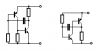
I never said that the data sheet limits Vce to 1.5 volts. I said that the 2 diodes across the transistor limit the voltage to 1.5. Didn't you understand I was talking about the circuit? You should read the posts better. The transistor does not get hit with 3 volts like you calculated earlier.
Yes, but what is the current? What is going to supply the excessive current you imply is going to exist? How long is the current going to last?
Do you really believe all the agitpap you put out?
Ratch
You're whole understanding of electronics is bogus. Vce(sat) is given on the data sheet as .25 volts, and that's consistant with pretty much all transistors. You will NEVER find a datasheet that lists says VCE is limited to 1.5.
I never said that the data sheet limits Vce to 1.5 volts. I said that the 2 diodes across the transistor limit the voltage to 1.5. Didn't you understand I was talking about the circuit? You should read the posts better. The transistor does not get hit with 3 volts like you calculated earlier.
No matter how low vce goes, the power that is dissapated increases with the current, and as every 10th grade physics student knows, power it I^2*R, I is current and R is the saturation resistance. You really should spend some time learning basic electronics before you try to appear to know what you're talking about, because you clearly don't.
Yes, but what is the current? What is going to supply the excessive current you imply is going to exist? How long is the current going to last?
You're whole understanding of electronics is bogus. You really should spend some time learning basic electronics before you try to appear to know what you're talking about, because you clearly don't.
Do you really believe all the agitpap you put out?
Ratch