Electro Tech is an online community (with over 170,000 members) who enjoy talking about and building electronic circuits, projects and gadgets. To participate you need to register. Registration is free. Click here to register now.
Welcome to our site! Electro Tech is an online community (with over 170,000 members) who enjoy talking about and building electronic circuits, projects and gadgets. To participate you need to register. Registration is free. Click here to register now.
Thanx again.
It seems the CMOS idea was misleading. (I was just hoping to build a more robust set-up, so wires don't get pulled accidentally etc. I need - are they called/ - D plugs, so the leads going in and out can be disconnected from the board. I was told a CMOS inclusion would be a benefit).
Darlington: Does the MJ11016 do the job of the two transistors that I have?
Now that I think about it almost one complete power stage can be removed depending on the pulse timing of fire and hold. If you are still there can you post a timing diagram of the 2 pulses?
I'm quite happy with the timing. Typically, I fire the Auxiliary 20 deg after the Main, if I use it. But mostly, I have the Aux switched off.
20 deg at 2500rpm = 1.3 msec, I think. But that bit is OK.
(Appreciate your help overall).
The whole circuit is on malcolmcochran.wordpress.com under Delphi control circuit.
It's in three diagrams, going from pulse capture, via timer, to igen.
What I was trying to say is I think instead of tying the two outputs together at the injector you could tie the two (fire and hold) together at the base of the BD711.
After re-reading you can't eliminate the 100 and 33 ohm resistors or the current limit will be to low.
If you know the DC resistance of the injector that number would help. Knowing that number we could add a small resistor (say 50 ohms) in series with the 220 ohm pot so that if it is adjusted to low the current limit would still work.
I'm loving this. Specially depth of your looking. When I asked the guy who'd designed the circuit if I could eliminate the 100R and 33R, he got quite annoyed So I'm glad both he and you agree!!
(He is an elderly man with terrible lung disease who gets little help from his MDs. He gets very impatient and has good days and bad days - mostly bad).
If I rebuild the electronics layout to be more "finished and robust", it would be with his blessing. I can only say, "Would it be OK to do such and such?" I might lose his goodwill (expensive as it is!) if I tried a change without his approval.
The resistance of the injector I used to know - it's very low indeed. Can't remember right here. But we do need a big charge. We ran at 12V initially and it just doesn't open fast enough.
Separate Q. When I put the current through the solenoid, I get a big field. (Direction matters because the valve is polarised N-S). When I collapse the current, I get a big EMF (??) - anyway, field - which sets up a new current. Is that in the opposite direction to the original? (There's a double negative in the argument which confuses me). The big diode around the injector is there to allow Earth to neutralise such a current. Right?
The injector mechanism is very clever. Everything is tiny. Huge pressures, tiny bleeds. You have to open the valve fast enough to "beat the bleed" then the needle rises incredibly fast and the fuel sprays in likewise. So these <msec currents are reflected in <msec hydraulic response times.
I'll look at what you are saying about the positioning of the output lines. Sounds OK.
One thing I'd like: little plugs a bit like those they used to have on PCs before USB ports. Or just four small 3 or 4 pin plugs and sockets. It would be good just to have to be able to detach floating leads from the circuit board. Oddly, I can't find anything. Any ideas?
One thing I'd like: little plugs a bit like those they used to have on PCs before USB ports. Or just four small 3 or 4 pin plugs and sockets. It would be good just to have to be able to detach floating leads from the circuit board. Oddly, I can't find anything. Any ideas?
I'm loving this. Specially depth of your looking. When I asked the guy who'd designed the circuit if I could eliminate the 100R and 33R, he got quite annoyed So I'm glad both he and you agree!!
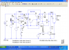
Here is the idea to combine both the fire and hold circuit into one. Sorry it's a little messy. I used the darlington to reduce parts count.
I suspect you got to the circuit you have with some experimentation that we don't have the benefit of, but hopefully your friend can keep you out of trouble.
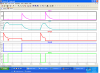
If you look at the simulation you can see that the current thru the coil during turn off is in the same direction as the current that opens it. That current circulates thru the diode. The effect of this is to keep the valve open longer than the pulse width. Don't know if you have this as a problem or not. It looks like the damper pulse may be an attempt to help this.
Basically this circuit just sums the current from fire and hold earlier. I hope I understood the timing of the two pulses. The first pulse in the simulation is fire and hold, the second fire only. I raised the current limit slightly to make sure you can get the full 16 amps. If you think you might build it I would be curious to know the use of the 560 and 1k resistors in your schematic. I might guess they supply just enough current for the valve to function. If so we should keep them.
Are you thinking of putting the high current thru the connector or just the 3 signal lines?
Here's a further simplification, eliminating one igen as suggested above. R4 and R5 can be adjusted to vary respectively the 'hold' current and the 'fire' current.
Nice circuit alec_t. Before I looked past the first page, I promise, I had almost the same circuit, except for the two current levels. Let the 2N2905 control the current and the FET do the switching/regulation.
A matter of knowledge (lack of, in my case): on both igen circuits, there's a transistor whose purpose I don't understand - it's the 2TX653.
And... it seems to have a base voltage of 1/3 total, ie ~6v. I thought they could only have voltages up to 0.6 v. Or at any rate, didn't do anything extra above 0.6v.
The first pulse in the simulation is fire and hold, the second fire only.
The other way round. The high brief current opens ferrite in the coil fast, the lower current is left holding it.
I was worried about the Turn Off Current delaying things. My friend showed on the scope that pulse duration was as predicted. But we were not testing with the Coil in place. It's possible we are delaying Closure. But I think not, because if I turn the timer down, I get no Opening ie the whole duration is too short for the thing to act at all, even tho the charge is max.
It's all food for thought.
Brilliant stuff.
Glad I didn't discover this board 5 years ago. Might have been tempted to "try this at home."
BTW, I notice these beautiful symbols on the RHS. What's the one that looks a bit like Pi or a Stonehenge?
The 2TX653's are over current protection. If the current goes over 14 amps they turn on and limit the current to about 14 amps.
I made the simulation with fire and hold and fire only as sometimes you run it without the hold current.
If you look at the current thru L1 (the injector) you can see it takes time to build up due to the inductance of the coil. It is also slow to decay because of the diode snubber. There is not much that you can do to speed up the turn on except to use a higher voltage (say 36 instead of 24 volts. The turn off can be improved, if it's a problem, by using a different type of snubber.
The little circles are signal sources for the simulation.
Sorry to be the bearer of bad news but I've spotted that the TI link in post #38 quotes "Fuel injectors appear as 8.5 mH inductor with 16.4 Ω series resistance when running hot."
I note that in post #36 you say "But we were not testing with the Coil in place."
So, unless your fuel injector inductance/resistance are drastically different from those figures I think your friend will find that the circuit as in the post #3 link (and post #4 attachment) won't work as expected when driving a real-world injector.
I've plugged the TI figures into an LTSpice simulation (using approximately equivalent simulated components to those in that circuit) and come up with the attached results. The maximum possible (resistance limited) injector current available from a 24V supply will be 24/16.4 = ~ 1.5A, but with a 1mS 'fire' pulse the current will only reach ~ 1.2A (limited by the inductance), regardless of the variable resistor settings. Decay time at switch-off is ~ 1.5mS.
The only way to get anything like the ~14A that you want is to use an injector of very low inductance and resistance and/or a much higher voltage supply. (Note that in my suggested circuit I assumed L = 50uH, R = 0.1 Ohm).
is there a simple way to estimate the inductance of the solenoid? I suppose it would need a time base scope.
I assumed L = 50uH, R = 0.1 Ohm.
At the start, several years ago, the inductance was allegedly estimated but I can't find the record. It was "very low". I found this unexpected 'cos of what it did.
But cars don't build high voltages and our destructive examination of the EMU for the injection system didn't suggest otherwise (which we did not copy at all; we started from scratch).
Yet we needed 18 v minimum to get it to Fire. And about 15A in rehearsal without it in place.
This site uses cookies to help personalise content, tailor your experience and to keep you logged in if you register.
By continuing to use this site, you are consenting to our use of cookies.

") So I'm glad both he and you agree!!
So I'm glad both he and you agree!!